42 hvac systems diagram
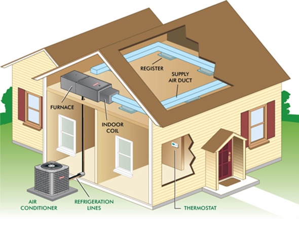
HVAC System Basics For Beginners - Warner Service The furnace. The furnace takes up a majority of the space in an HVAC system. It's usually in the basement, and it's an important component. The furnace moves air from the heat exchanger into the air ducts. The furnace is usually confused with boilers, but they're different HVAC appliances. HVAC System Diagram: Everything You Need to Know | Gee Heating An HVAC system consists of two different parts, the indoor and the outdoor components. When you walk by homes in your neighborhood or even by businesses in urban parts of the city, you'll see a big box either behind the home or on top of the business. This is just one-half of the larger HVAC system. The Air Conditioner Equipment. The outdoor component is the air conditioner equipment.
HVAC Diagram - Online Drawing Tool - Engineering ToolBox FREE online HVAC diagram drawing template - enabled for the FREE online Google Drive drawing tool. No installation is required - just log in to your Google Account (Google Accounts are free) and copy ("File > Make a copy") this online HVAC drawing template to start making your own drawing. Select, copy and paste the components you want to use - customize existing components to make new ones.
Hvac systems diagram
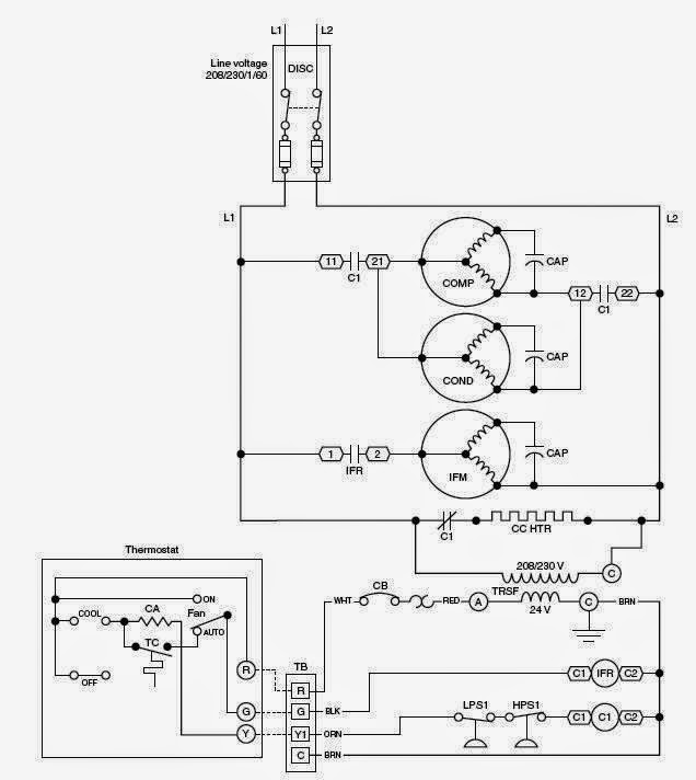
HVAC - Heating, Ventilating, and Air Conditioning Block ... Heating, ventilation, and air conditioning (HVAC) systems are becoming more sophisticated as manufacturers design features into the product that make them more reliable, quieter, more efficient, and with a higher comfort level in ambient temperature. Texas Instruments offers products to meet the needs of these higher performance systems. PDF HVAC Systems: Overview HVAC Systems: Overview Michael J. Brandemuehl, Ph.D, P.E. University of Colorado Boulder, CO, USA Overview System Description Secondary HVAC Systems Air distribution Room diffusers and air terminals Duct Design Fan characteristics Air Handling Units Water distribution Cooling coils Pipes and pumps Primary HVAC Systems Electric chillers How to Read HVAC Drawings 4: Control Panel Diagram ... The control circuit diagram shows how the system is controlled. Electrical components such as overload relays, selector switches, indicating lamps and timers are found in the control circuit diagram. Following is an HVAC outdoor air fan control circuit diagram with the function of each component labeled:
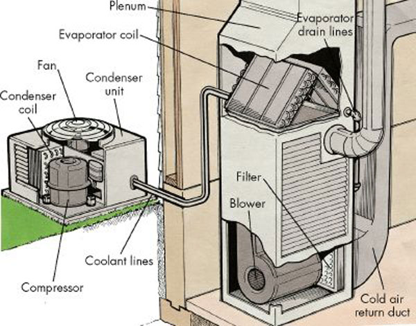
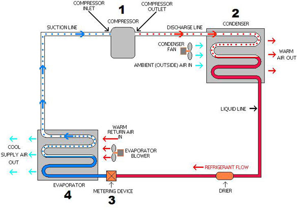
Hvac systems diagram. Understand Basic HVAC Electrical Components & Wiring in ... To keep track of wiring, HVAC technicians rely on circuit schematics or visual representations of wiring programs. There are three basic types of circuit schematics used in HVAC today. They are the Line Diagram, the Ladder Diagram, and the Installation Diagram. You can think of these circuit schematics as road maps. How Do Air Conditioning Systems Work in a Car? AC System Diagram. Below is an AC system diagram that shows the main components used and how they're connected: Common AC System Failures. Because automotive air-conditioning systems operate under pressure, they need to remain completely sealed from the surrounding environment. Anything that allows refrigerant to escape or contaminants to ... Anatomy Of A Central Air Conditioning System - Altitude ... EVAPORATOR COIL. This is the piece of your air conditioning system that most people never see. It's contained in a metal box called a plenum, and sits on top of your furnace. If you have a horizontal furnace in an attic, the evaporator coil will sit on one end of the furnace instead of on top. The 'inside unit' or 'indoor coil' are ... PDF HVAC - System Airflow Diagram Guidelines The HVAC System Airflow Diagram is intended to depict the distribution and conditioning of all central HVAC air systems. All heat addition, humidification, dehumidification and cooling components are to be incorporated into the System Airflow Diagram. ...
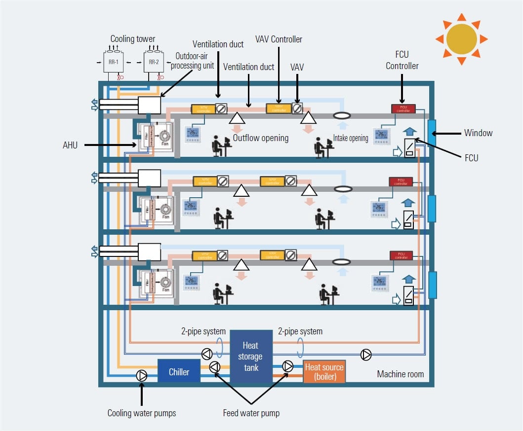
PDF Chapter 18 MECHANICAL (HVAC) DRAWINGS AND DESIGN SECTION ... 1806.2 Combined Drawings: HVAC Systems and piping systems for HVAC systems may be combined on the same set of drawings where practical and prior written acceptance form the Project Manager has been issued. Section 1804 Flow Diagram Requirements and Section 1805 Drawings for Piping shall apply to the HVAC drawings as needed. Hvac Wiring Diagrams 101 - easywiring Hvac wiring diagrams 101. Warning death personal injury and or property damage hazard failure to carefully read and follow this warning. The first and most common is the ladder diagram so called because it looks like the symbols that are used to represent the components in the system have been placed on the rungs of a ladder. How Air Condition Ventilation & Furnace Works - HVAC AC ... Here is my understanding of a HVAC system. I am not a professional, just documenting this and sharing my knowledge. Any comments is appreciated. Thanks for w... Heating, Ventilation and Air-Conditioning Systems, Part of ... Potential for Natural Ventilation and Operable Windows. In some parts of the country, where temperature and humidity levels permit, natural ventilation through operable windows can be an effective and energy-efficient way to supplement HVAC systems to provide outside air ventilation, cooling and thermal comfort when conditions permit (e.g., temperature, humidity, outdoor air pollution levels ...
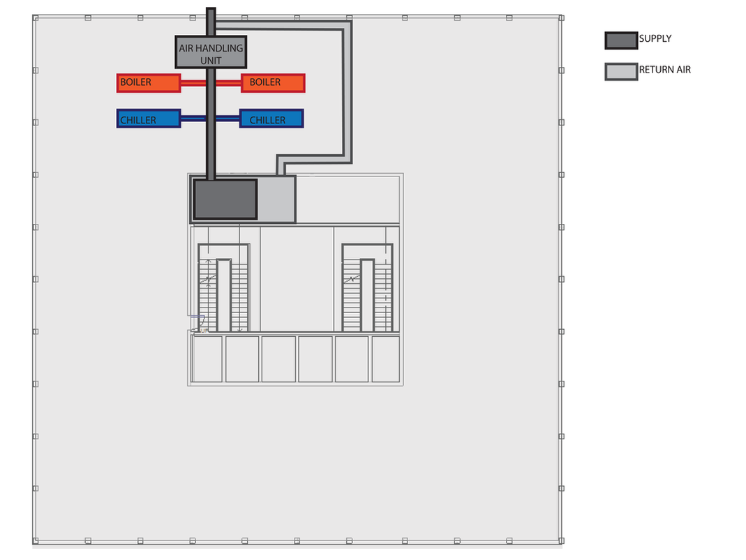
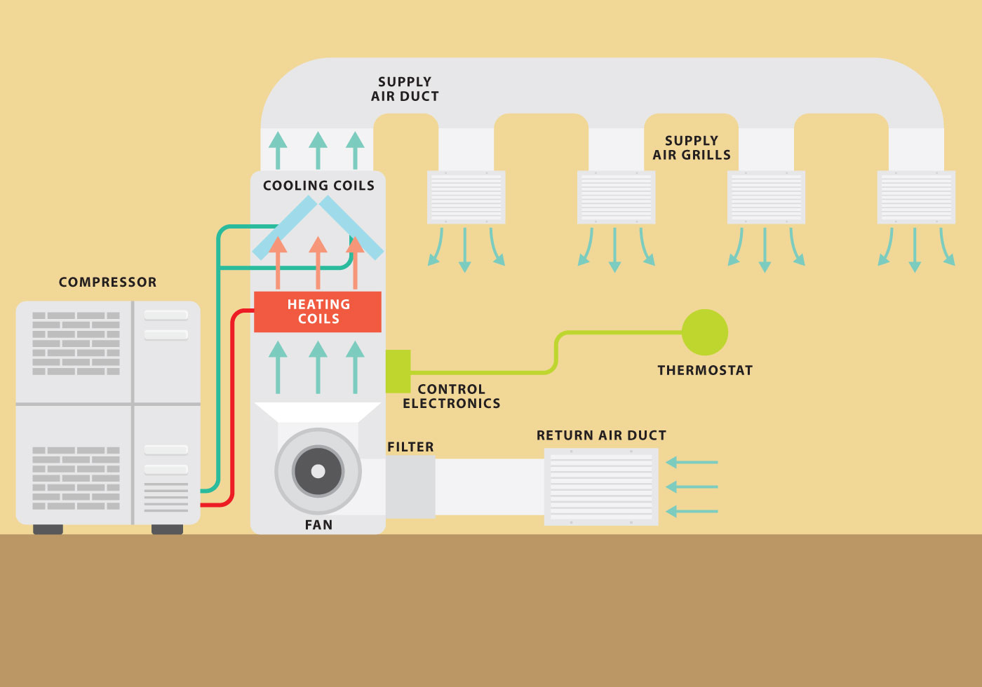
Thermostat Wiring Diagrams Quality HVAC Guides 101 Thermostat Wiring Diagrams - Heat pumps are wired for HVAC control far differently than air conditioning systems so make sure you know the difference and correctly identify the type of HVAC system you have installed. Additionally, before you decide to change your thermostat, make sure you have the correct tools especially a screwdriver and wire pliers. How Does an HVAC System Work? [Diagram] - The Severn Group How Does an HVAC System Work? The term HVAC stands for heating, ventilation and air conditioning, a system used to control the temperature in a space as well as humidity and quality of air. In a big building, the system needs to be able to function based on comfort need as well as meet the size of the space. What is HVAC ? Types, Parts & Diagram (Easy Guide ... HVAC System Parts and Diagram Image from 21celcius. There are different parts for a HVAC system based on its application, but one can consider what occurs in a evaporative cooling system as a widely used case throughout the world and get a sense of what is generally happening in the system. The logic for heating is in a way similar and can be ... Air conditioning- Types, Diagram, Working, Applications Components of the air conditioning system. The basic components of the air conditioning system are, 1. Fans: For circulation of air 2. Filters: For cleaning air 3. Heating element: Heating of air (It may be an electric heater, steam, hot water) 4. Control system: It regulates automatically the amount of cooling or heating. 5.
CU Faculty
PDF HVAC Variable Refrigerant Flow Systems There are a wide range of air conditioning systems available, starting from the basic window-fitted units to the small split systems, to the medium scale package units, to the large chilled water systems, and currently to the variable refrigerant flow (VRF) systems.

Schematic diagram of the HVAC system and its control system ...
Schematic Diagrams for HVAC Systems - Modernize Schematic Diagrams for HVAC Systems: What You Need to Know. February 22, 2022. If you know a little bit about home heating and cooling systems, you probably realize that they are pretty complicated little systems! Inside those compact units are electrical connections, fans, compressors, condensers, switches, coolants—the list goes on and on.

HVAC Zoning 101 & Smart Zoning – Keen Home
PDF Fundamentals of HVAC Control Systems - Semantic Scholar Control Diagrams and Symbols Symbols for HVAC system components Refer to ASHRAE Fundamentals Handbook 2005 Chp. 37, Abbreviations and Symbols Refer to other local standards or guidelines Usually specified in the contract drawings & documents Generic control diagrams Using generic symbols to describe and define the

Commercial HVAC Systems - Service & Repairs - Orange County ...
How a Central Air Conditioner Works - HomeTips Diagram of a central air-conditioning system of a house including a network of warm air and cold air ducts. ©Don Vandervort, HomeTips. A central air conditioner is like a giant refrigerator for your house. In fact, it employs the same types of components, materials, and systems as a refrigerator, including a refrigerant that changes from ...

19 Mechanical Design ideas | mechanical design, hvac design ...
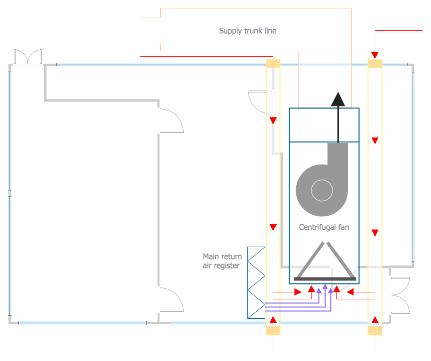
Hvac for Beginners This Hvac For Beginners section begins here with a discussion about forced air duct systems, the basics, the how and why of duct sizing. Ductwork is simply an air delivery system. A delivery system for all forced air systems, furnace or air handler, heating or air conditioning, or both.

What Is Geothermal HVAC and How Does It Work? - Refrigeration ...
Ductwork layout | HVAC Plans | Design elements - HVAC ... This HVAC floor plan sample shows the ventilation duct system layout. "Ducts are used in heating, ventilation, and air conditioning (HVAC) to deliver and remove air. The needed airflows include, for example, supply air, return air, and exhaust air. Ducts commonly also deliver ventilation air as part of the supply air.

Voltas 5 Star HVAC AC System Diagram, For Industrial Use ...
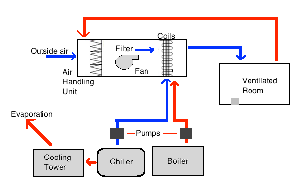
PDF Introduction: Hvac Basics Starting at point A on the diagram above, return air passes through the filters on the system and is drawn into the supply fan. The air is then pushed into the dual duct section of the unit. It will now separate into two ducts, one that will handle the heating functions and one that will handle the cooling functions:

HVAC Drawings | Restaurant/ Bakery HVAC Design
What is Air Conditioning System? Diagram, Applications ... An HVAC system consists of heating, ventilation, and air conditioning. The air conditioning system also consists of so many parts. In this article, we also see the basic diagram of an air conditioning system to understand its working principle easily.
Anatomy Of A Central Air Conditioning System - Altitude ...
Central heating diagram - Mike the Boilerman Combi system. This diagram illustrates how simple the heating system connected to a combi boiler is. No external pump, no tanks, no external expansion vessel, no motorised valves and in many cases item 6 is not needed either. (An automatic bypass valve is fitted inside most combi boilers by the manufacturer these days.)
HVAC Plans | Create Block Diagram | HVAC Marketing Plan ...
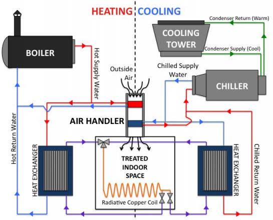
HVAC System Components & How They Work ? | Linquip The following diagram shows a working cycle in an HVAC system, that could be intended for both heating and cooling applications by changing where the heat is absorbed from and where it is rejected to. HVAC stands for Heating, Ventilation, and Air Conditioning; therefore, the design of such systems is mostly accompanied by some air ventilating and cleaning processes that are integrated with these systems.

Sample HVAC System Diagram from Protecting Building Occupants
Electrical Wiring Diagrams for Air Conditioning Systems ... 3- Types of Electrical Wiring Diagrams For Air Conditioning Systems. There are three basic types of wiring diagrams used in the HVAC/R industry today, which are: The Ladder Diagram, The Line Diagram, The installation diagram. 3.1 The Ladder Diagram.
File:HVAC system diagram.jpg - Wikimedia Commons
How to Read HVAC Drawings 4: Control Panel Diagram ... The control circuit diagram shows how the system is controlled. Electrical components such as overload relays, selector switches, indicating lamps and timers are found in the control circuit diagram. Following is an HVAC outdoor air fan control circuit diagram with the function of each component labeled:
How does air conditioning work? – Heating, Air Conditioning ...
PDF HVAC Systems: Overview HVAC Systems: Overview Michael J. Brandemuehl, Ph.D, P.E. University of Colorado Boulder, CO, USA Overview System Description Secondary HVAC Systems Air distribution Room diffusers and air terminals Duct Design Fan characteristics Air Handling Units Water distribution Cooling coils Pipes and pumps Primary HVAC Systems Electric chillers

What is HVAC? | A Little Design Help
HVAC - Heating, Ventilating, and Air Conditioning Block ... Heating, ventilation, and air conditioning (HVAC) systems are becoming more sophisticated as manufacturers design features into the product that make them more reliable, quieter, more efficient, and with a higher comfort level in ambient temperature. Texas Instruments offers products to meet the needs of these higher performance systems.
HVAC Single Line Diagram - AE - 391: AE Design II - Winter 2015

Vehicle HVAC System - MATLAB & Simulink

HVAC-System-Diagram - (270) 842-6125

What is HVAC? | Heating, Ventilation, and Air Conditioning ...

HVAC system schematic diagram | Download Scientific Diagram

Modeling techniques used in building HVAC control systems: A ...

The HVAC system diagram from PEIDE-HVACAQUA.COM

Brief Idea On HVAC System – A Complete Phrma Solution
Simulating HVAC System Designs for a Powerhouse Air ...

A guide to HVAC System Design | Cooling India Monthly ...

Basics of HVAC System : Pharmaceutical Guidelines

6 Schematic diagram of HVAC system | Download Scientific Diagram

Hybrid system based adaptive control for the nonlinear HVAC ...
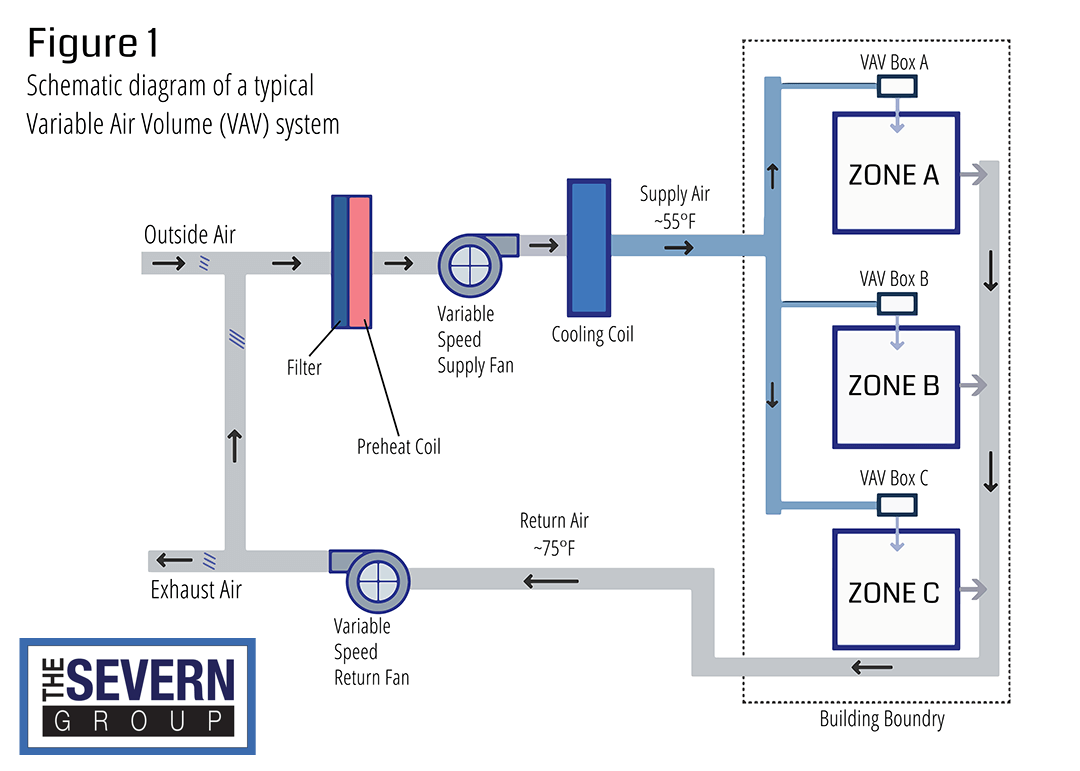
VAV vs VVT HVAC Systems - The Severn Group
What is HVAC ? Types, Parts & Diagram (Easy Guide) | Linquip
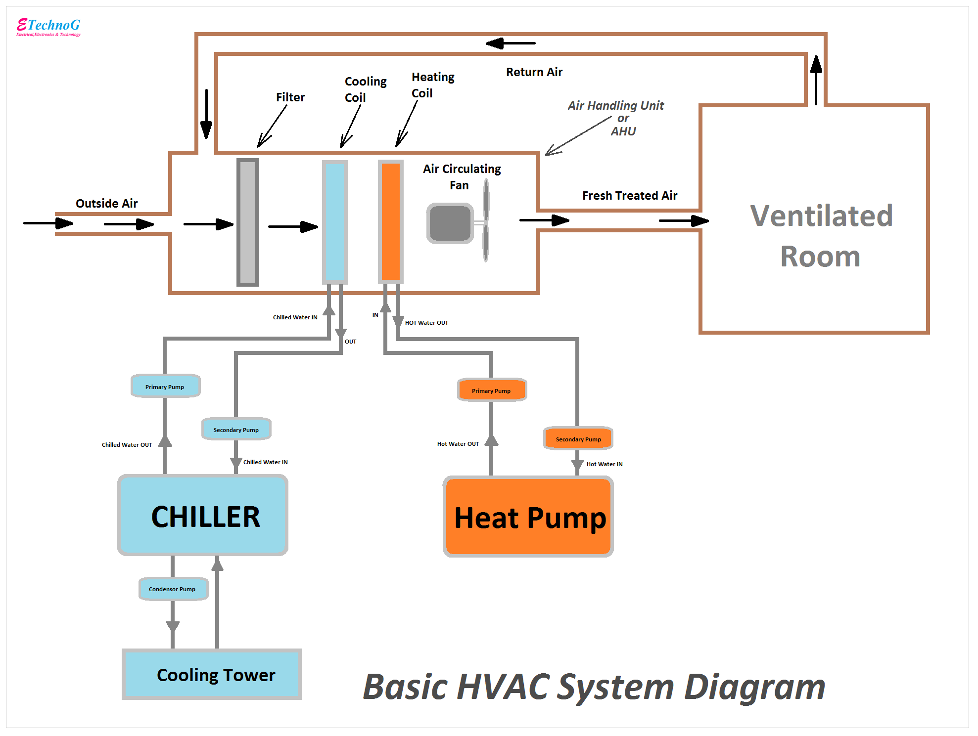
Basic HVAC System Diagram with important Parts and Components ...
Understanding the HVAC Systems Basics, Work & Types in 2022
:no_upscale()/cdn.vox-cdn.com/uploads/chorus_asset/file/19521285/air_handler.jpg)
Central Air Conditioning Systems: A Guide to Costs & Types ...
Hvac System Vector Graph 106090 Vector Art at Vecteezy
![hvac system schematic [5]. | Download Scientific Diagram](https://www.researchgate.net/profile/Nathalie-Cauchi/publication/327136294/figure/fig1/AS:663796641185792@1535272860265/hvac-system-schematic-5.png)
hvac system schematic [5]. | Download Scientific Diagram

HVAC System Types Part 1
Schematic Diagrams for HVAC Systems - Modernize
HVAC Systems | Renesas
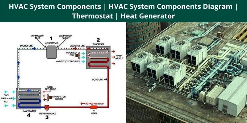
HVAC System Components | HVAC System Components Diagram ...

HVAC - Heating, Ventilating, and Air Conditioning Block ...

DYNAMIC SYSTEMS

Schematic Diagrams for HVAC Systems - Modernize

Assessing the energy efficiency improvement potentials of ...


Comments
Post a Comment