43 stirling engine pv diagram
became more popular. The Stirling engine continues to attract attention, periodically, as a more fuel e cient and potentially cleaner engine for some applications. Currently, the primary application of Stirling cycles is in refrigeration. The Stirling Cycle The pV diagram for an ideal Stirling cycle is shown in Fig (2). In our setup, two pistons [video](https://www.youtube.com/watch?v=DfWaREBx_UQ) Particularly in the parts where the gas is expanding(2 -> 3) or compressing(4 -> 1). Correct me if I'm wrong but the sign of **work** depends on what prespective we're doing the calculations (system vs environment). In this video, he seems to be doing all of the calculations from the environment perspective since for the expansion(around 7:33), he designates his work term to be negative. since thermal energy is positive and work is neg...
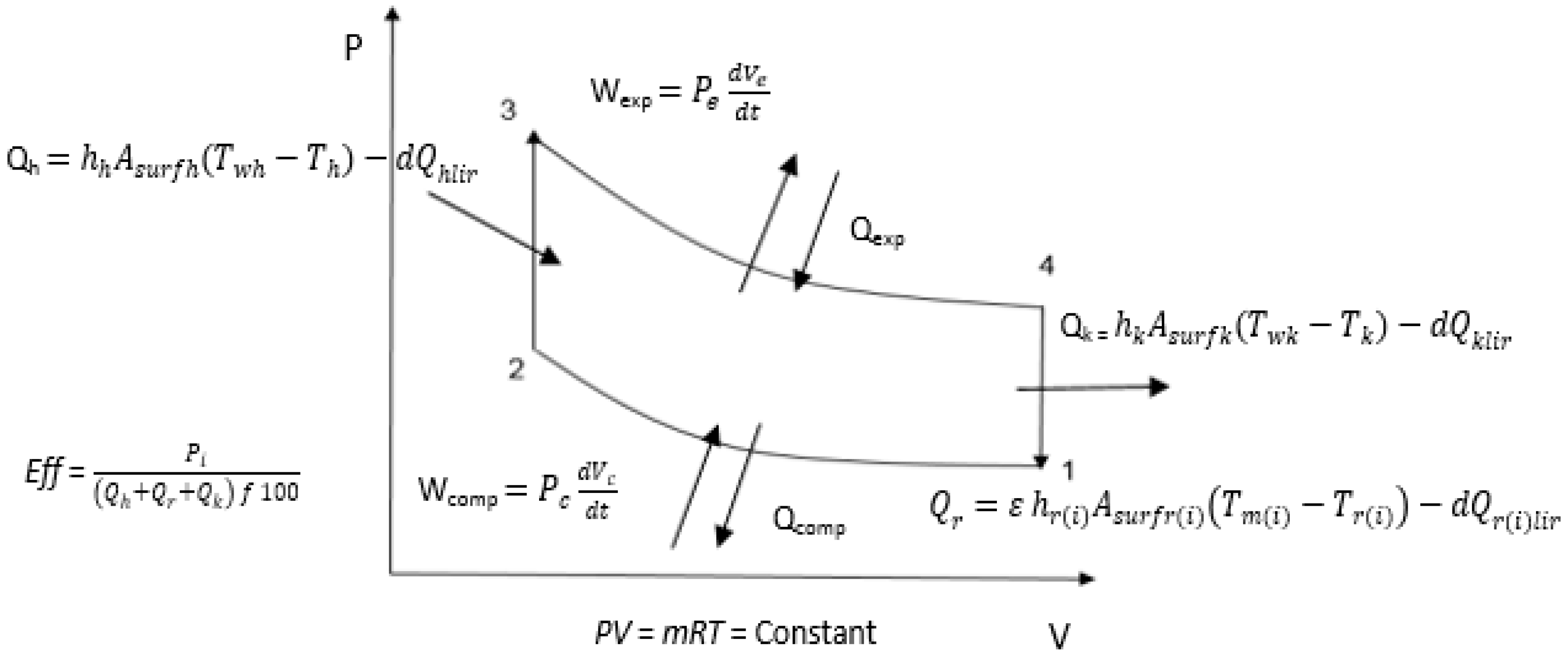
Mar 22, 2018 · PV Diagram of a Real Cycle. PV diagram of a real Stirling cycle; four angular positions of the crank of the machine that executes the cycle are indicated. The actual cycle can be represented on a pressure-volume (PV) diagram as a closed curve with a shape; this curve represents, with different values of pressure and temperature, most of the real Stirling cycles.

Stirling engine pv diagram
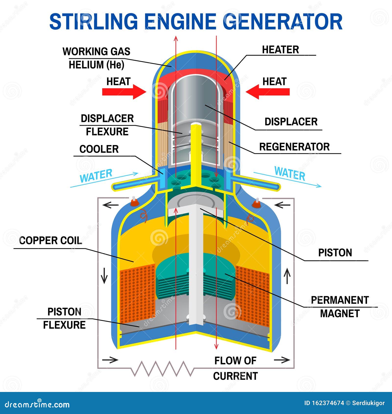
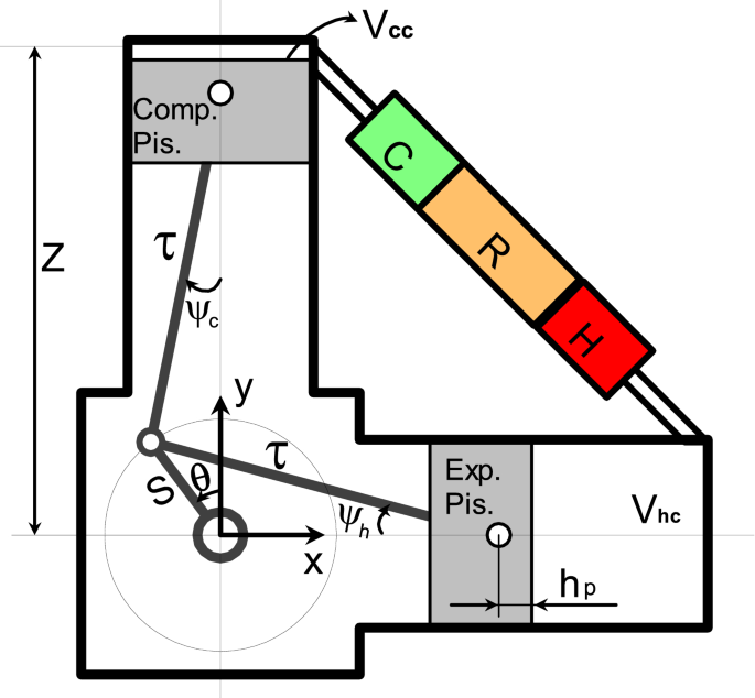
a Stirling engine to function as an electric generator. Stirling engines operate on a regenerative thermodynamic cycle where the working fluid is enclosed within the engine. Fluid flow is modulated by changing volumes within the engine. The two pistons of the engine are exposed to a hot source and cold source, respectively. The performance of the engine can be calculated using a P-V diagram. The volume in the engine is easily calculated by using the internal geometry. When the volume, mass of the working gas and the temperature is decided, the pressure is calculated using an ideal gas method as shown in equation (1). (1) The engine pressure can be calculated under following … A PV diagram's Y axis shows pressure (P) and X axis shows volume (V). The area enclosed by the loop is the work (W) done by the process: This work is equal to the balance of heat (Q) transferred into the system: Equation (2) makes a cyclic process similar to an isothermal process: even though the internal energy changes during the course of the cyclic process, when the …
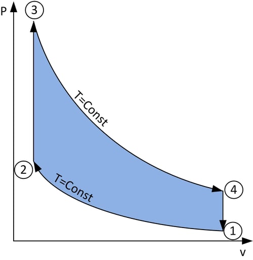
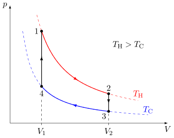
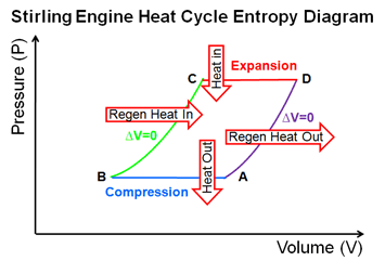
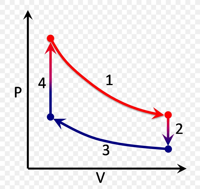
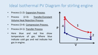
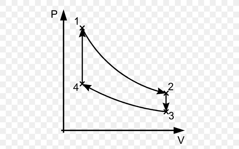
Stirling engine pv diagram. PV Diagram of Stirling Cycle A Stirling engine works on the Stirling cycle. A Stirling cycle works in the following way: Isothermal Expansion Isochoric Heat removal Isothermal Compression Isochoric heat addition Stirling Cycle 1) Isothermal expansion (line 1 to 2) Stirling cycle is one ideal cycle for the operation of Stirling engine. First we will see here the PV and TS diagram for Stirling cycle, we will understand here the various processes involved and finally we will determine the thermal efficiency of the Stirling cycle. ideal Stirling cycle. P-V diagram Figure 2 shows the experimental setup used to simultane - ously measure the pressure and volume of the displacer-type Stirling engine. Pressure measurement — To monitor the pressure change of the gas in the Stirling engine, an inexpensive differential pressure sensor was pur - chased. May 12, 2020 · The p-v and t-s diagram of this cycle are shown in the figure. Let us now consider the four stages of the Stirling cycle. Let the engine cylinder contain m kg of air at its original position represented by point 1. At this point, let P1, T1, and V1 be the pressure, temperature, and volume of the air respectively.
**Process Flow Diagram:** https://preview.redd.it/pwp6kssnldc81.jpg?width=5313&format=pjpg&auto=webp&s=3cf24795d5ca2644f6cd12d5b11bc80da6756a5d ​ This system is designed to perform a baseline ore processing chain through: 1. Universal Macerator 2. Ore Washing Plant 3. Thermal Centrifuge 4. Universal Macerator 5. Combine partial byproducts into full dusts 6. Output final products / bypass any materials that are not designated for processing Additional system functiona... Download scientific diagram | PV and Ts diagram of Stirling engine cycle. from publication: Theoretical and experimental investigation of Alfa type bio mass Stirling engine with effect of ... A PV diagram's Y axis shows pressure (P) and X axis shows volume (V). The area enclosed by the loop is the work (W) done by the process: = This work is equal to the balance of heat (Q) transferred into the system: = = Equation (2) makes a cyclic process similar to an isothermal process: even though the internal energy changes during the course of the cyclic process, … A Stirling engine is a specific flavor of heat engine formulated by Robert Stirling in 1816; this means it can transform the flow of heat into mechanical work (such as spinning a crankshaft). The key term is "flow of heat"; there must be two "reservoirs" that are separated, and these reservoirs must be at different temperatures in order ...
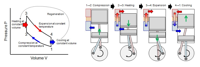
A p - V diagram of the Stirling cycle is depicted in Fig. 5.1. It consists of four processes: isothermal compression with heat removal 1 → 2, isochoric heat addition 2 → 3, isothermal expansion with heat addition 3 → 4, and isochoric heat removal 4 → 1. Thus, we have T1 = T2, V2 = V3, T3 = T4, and V4 = V1. Use summer's sunlight with photovoltaic panels to make methane from water and coal or wood and cool it to liquid. In winter, before being pumped for heating, that extreme coldness of liquid methane can make stirling engine more efficient. Methane boils with that energy extraction, gives kinetic energy for generator's electricity production and goes in pipes in gaseous form. Stirling engine is a closed cycle regenerative heat engine. It works on either air or any other gas. Stirling cycle is invented by Robert Stirling with help from his brother (in 1816). Below are P-V and T-S Diagrams of the Stirling Cycle. Stirling Cycle is comprised of four processes Process 1-2 It is isothermal heat addition process. I just finished a final with a UML diagram question and was just wondering.
Heat Engine PV Diagram. Heat engines can be typically illustrated on a PV diagram, Pressure-Volume (PV) diagrams are the basic tool for the study of heat engines that use gas as the working substance.PV diagram will be a closed-loop for a cyclic heat engine. The area of the loop is the representation of the amount of work done during the cycle. The idea of the efficiency of an …
04.11.2018 · 2000 Chevy Truck Engine Diagram Silverado 2500 Vs 2500hd Catalytic 1982 Chevy Truck Fuse Diagram Wiring Diagram T1 Silverado Drawing Nova Picture 1474764 Silverado Drawing Nova General Motors Engine Guide Specs Info Gm Authority 2014 Silverado Lt Z71 Drl Fuse Chevrolet Forum Chevy Maintenance Repair Questions I Have A 94 Silverado With A 5 7 …
A Stirling engine is a type of a heat engine that runs when a temperature difference is applied between the top and bottom plates of the engine body. In this...
PV Diagram. It is the pressure-volume diagram which helps to study and analyze the efficiency of a heat engine. It acts as a visualization tool for the heat engine. As we know that the working substance will be any gas, the PV diagram explains the visuals from the heat engine by considering the ideal gas law. Even though the temperature may ...
Transcribed image text: Question 4 An ideal Stirling engine thermodynamic cycle is illustrated in the PV diagram below. The cycle consists of two isochoric and two isothermal processes. The temperature of the cd process is at 23°C. Consider the gas in the Stirling engine to be a monatomic ideal gas.
There were basic two graphs for Stirling engine such as P-V diagram and T-S diagram shows in Figure 4. By referring this diagrams can understand how Stirling engine cycle operate. There were three...
As a gas cycle, the Stirling Cycle is usefully characterized by a P-V diagram, a plot of the internal pressure versus internal volume over a single cycle of the engine. An illustrative P-V diagram is shown in Figure 1.2.
The Stirling cycle is a thermodynamic closed cycle that was invented in 1816 (!) by a Scottish minister, Robert Stirling. Request more information. It was used in the so-called hot air engine, which was considered at the time to be capable of replacing the steam engine. This was partly because the boilers used in early steam engines were prone ...
Stirling PV diagram typical of a real engine. Note the rounded corners. Image courtesy Comsol. The moving parts of all high-speed machines need to have a smooth motion, or the machine will tear itself apart. High-speed engines of any type will have a PV diagram that looks round on the edges like this one
A Stirling engine is a heat engine that is operated by the cyclic compression and expansion of air or other gas (the working fluid) at different temperatures, resulting in a net conversion of heat energy to mechanical work. More specifically, the Stirling engine is a closed-cycle regenerative heat engine with a permanent gaseous working fluid. Closed-cycle, in this context, means a ...
Stirling Refrigerator. History In 1834, noted British astronomer John Herschel applied the Stirling cycle for cooling. This was the first known case of using the Stirling machine for refrigeration purposes. Later, Scottish born John Gorrie may have been the first to apply the Stirling machine for making ice. From descriptions published in 1876 ...
The Stirling engines can function as a work producing device or work consuming device [11].This brings irreversible operation flexibility. The schematic diagram of the Stirling cycle operation is shown in Fig. 4.5.The source of high-temperature heat can be concentrated solar, biomass combustion or any waste heat.
28.11.2021 · P-v and T-s Diagram of Diesel Cycle. Let the engine cylinder carry m kg of air at point 1. at this point let P1 and T1 and V1 be the pressure, temperature and volume of the air. Following are 4 stages of an ideal diesel cycle. The ideal diesel cycle consists of two adiabatic, constant pressure and constant volume processes. These processes are represented on a P-v …
The Stirling cycle is a thermodynamic cycle that describes the general class of Stirling devices. This includes the original Stirling engine that was invented, developed and patented in 1816 by Robert Stirling with help from his brother, an engineer.. The ideal Otto and Diesel cycles are not totally reversible because they involve heat transfer through a finite temperature difference during ...
This was a project that was carried out by the previous student. The aim of this project is to improve the existing des.
This paper describes simple modifications to a demonstration Stirling engine that allows one to make quantitative measurements of the Stirling cycle. First, we describe measurements of the P-V diagram using an in-expensive pressure sensor and a common photogate. Then, as a supplement, the engine was run as a refrigerator by using a rotary tool ...
3.4 Ideal and conventional Stirling engines 51 3.5 Stirling engine control 55 3.6 Temperature control of Stirling engines 55 3.7 Pressure control of Stirling engines 55 3.8 Stroke control of Stirling engines 56 3.9 Phase control in Stirling engines 57 3.10 Dead volume control 58 3.11 Speed control 58 4. THE PROBLEM TO BE SOLVED 60
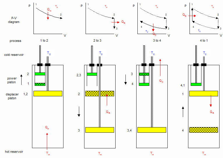
Heating and cooling is accomplished by the displacer motion, represented primarily by the vertical motion of the dot on the PV diagram. Clicking on the "Kinematic Stirling Engine" button displays a configuration in which the piston and displacer motion are caused by the mechanism at the bottom.
– Stirling Engine – Steam engine – Elastic engine. N S Scissor‐Lift Tea Candle Variable Length Plumb Rod (non‐ferromagnetic preferably) Neodymium Magnet Diagram of Apparatus. How it works! H: magnetic field intensity M: magnetization. How it works! 1: Bob is cool, but is heating up 2: Bob is Hot, It is losing its magnetization 4: Bob is cool, regaining its magnetization 3: Bob is …
Fig.3 pV-diagram of the ideal Stirling cycle. In the pV diagram (Fig.3) the corresponding cycle consists of two isotherms and two isochores. The volume V is the volume between the two pistons. In practice the cycle is not divided in discrete steps as described above. Usually the motions of both pistons are driven by a common rotary axes which makes the motions …
If the engine is driven by a motor, and the process curves in the T-s and P-v diagrams run counter clockwise, the Stirling cycle operates as a refrigerator and/or heat pump. The coefficient of performance for Stirling cycle is: H L H HP H L L f T T T COP T T T COP Re Note that the COP's of the Stirling cycle are the same as the Carnot cycle.
A Stirling engine is a type of a heat engine that runs when a temperature difference is applied between the top and bottom plates of the engine body. In thi...
So, Let us see here Ericsson cycle. First we will see here the PV and TS diagram for Ericsson cycle, we will understand here the various processes involved and finally we will determine the thermal efficiency of the Ericsson cycle. As we can see here from PV and TS diagram, there will be two reversible isothermal processes and two reversible ...
12.05.2020 · Carnot Cycle: Principle Processes, Efficiency with [P-v and T-s Diagram] Four Stroke Diesel Cycle Engine and Its Working [Explained with P-v and T-s Diagram] Stages of Rankine Cycle. The following are the four stages of an ideal Rankine cycle: Isothermal expansion; Adiabatic expansion; Isothermal compression; Warming operation; 1. Isothermal Expansion. …
Pictorial view of solar powered stirling engine 1.2 Objectives • To fabricate the model of solar powered Stirling engine. • To study the working mechanism of parabolic concentrated solar panel and Stirling engine. 1.3 Significances • Proper utilization of waste heat. • It can be used for mechanical purposes like water pumping, milling ...
I have been trying to wrap my head around the concept for hours as to how Stirling engines could be used for refrigeration, but no matter how much i try to understand it I just can't wrap my head around how a couple of moving postons and some gold mesh or whatever could make things cold. ​ How does this all work? I feel like there is just one thing I am missing to make this all "click" but I don't know what it is.
Now PV-diagram of the Stirling engine shown in Figure 2 can be examined in detail. The key points are that during expansion along path 1-2 there is no temperature difference so that the change in internal energy dU = 0. From the first law of thermodynamics heat added from the hot reservoir is the same as the work done by the system, Q H = W H.
A PV diagram's Y axis shows pressure (P) and X axis shows volume (V). The area enclosed by the loop is the work (W) done by the process: This work is equal to the balance of heat (Q) transferred into the system: Equation (2) makes a cyclic process similar to an isothermal process: even though the internal energy changes during the course of the cyclic process, when the …
The performance of the engine can be calculated using a P-V diagram. The volume in the engine is easily calculated by using the internal geometry. When the volume, mass of the working gas and the temperature is decided, the pressure is calculated using an ideal gas method as shown in equation (1). (1) The engine pressure can be calculated under following …
a Stirling engine to function as an electric generator. Stirling engines operate on a regenerative thermodynamic cycle where the working fluid is enclosed within the engine. Fluid flow is modulated by changing volumes within the engine. The two pistons of the engine are exposed to a hot source and cold source, respectively.











Comments
Post a Comment