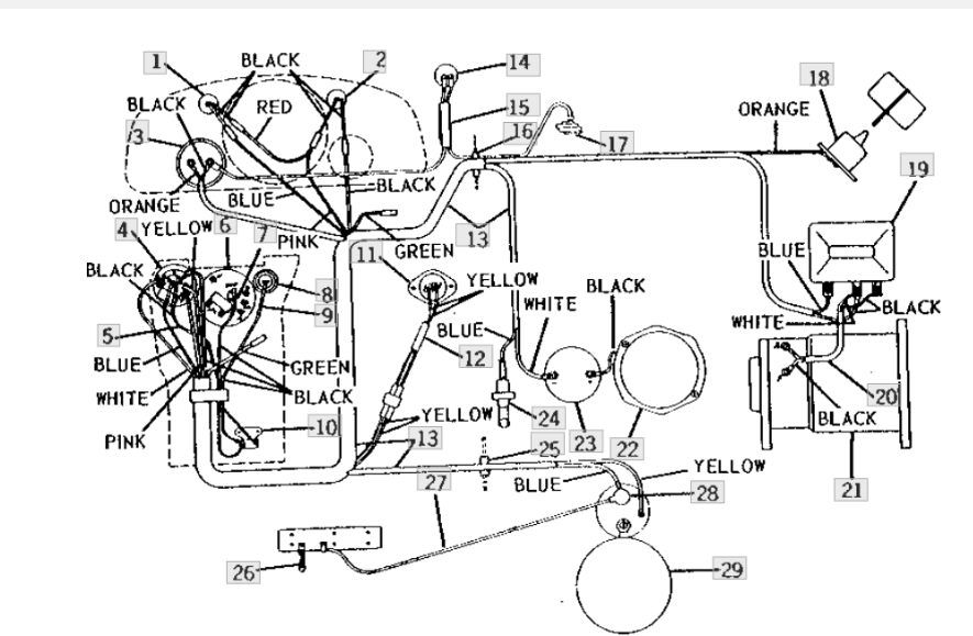
41 positive ground wiring diagram
CIRCUITS LABORATORY EXPERIMENT 9 Operational Amplifiers chassis ground, and connect the positive floating terminal on the right power supply to chassis ground. Use cables with banana plug connectors to supply the +16V, -16V, and ground to separate terminals on your solderless wiring fixture. Be sure to connect the ground cable to the ground terminal on the fixture. Then connect the +16 V to pin 7 and Pertronix Positive Ground Wiring - Pertronix Ignitor ... Pertronix Ignitor Wiring Diagram - pertronix ignition wiring diagram, pertronix ignitor ii wiring diagram, pertronix ignitor iii wiring diagram, Every electrical arrangement consists of various distinct parts. Each component ought to be placed and connected with other parts in particular manner. If not, the arrangement won't work as it ought to be.
Wiring Diagram Jds3462 Fuel Positive Ground Wiring Diagram Jds3462 Fuel Positive Ground. The Ignitor is designed for 6-Volt positive ground systems. 2. See Chart on back page for coil recommendations. 4. See figure B for wiring diagram. 2. Positive ground electrical system in old cars. Since the beginning of automotive history, both negative and positive ground polarity have been used by ...

Positive ground wiring diagram
How to Wire A Positive Ground One Wire Alternator ... Connect the one wire off the post on the new positive ground alternator with a 10 gauge wire to the top terminal of the ammeter as shown on your diagram. As I said in other replies if your electronic ignition was connected per the manufacturer and the tractor ran fine as you stated several times keep it connected as before and enjoy. How To Wire Fog And Driving Lights Harness Wiring Diagram Consult your local and state regulations regarding minimum and maximum mounting height above the ground or specific lighting requirements. Harness Wiring. Note: This is a general wiring diagram for automotive applications. Use as reference only. Your lamp kit harness my have different wire colors. Locate the low beam or high beam light lead on one headlamp by using a … 6volt positive ground question? - Technical - Antique ... With a positive ground system, the polarity is reversed from a negative ground system. In other words, the flow of electrons goes in the other direction. To get the polarity of the coil correct, the positive side of the coil goes to the points and the negetive side goes to the ignition switch. A distributor is divided in to two different ...
Positive ground wiring diagram. 6 volt positive ground battery ignition schematic ... On a 6 volt positive ground battery ignition the + goes to the distibutor. Last edited by Barnyard on Tue Jun 12, 2012 3:03 am, edited 1 time in total. There are two ways to get enough Cubs. One is to continue to accumulate more and more. Positive ground simplified - bugeyeguy.com Positive ground simplified. July 27, 2018 by bugeyeguy. Believe it or not, wiring a car with positive ground is supposed to make them rust less. Doesn't seem to work very well… my first car, a (positive ground) 1966 MGB came to me with rocker panels completely absent, as though they had vaporized. At the time the car was only 12 year old! Wiring Diagram for Positive Ground Dynamator w/Ammeter This wiring diagram is for use in the installation of a Dynamator in a Tcar wired for positive ground and an ammeter. The relay that is shown in the wiring diagram is provided by Accuspark for use in positive ground systems. The wiring diagram is shown with the permission of Mort Resnicoff. How Does a Positive Ground System Work? - Reference.com A positive ground system works by directly connecting the chassis of a vehicle to the positive side of the vehicle's battery. This system effectively earths the vehicle as the chassis attaches to the battery using a positive battery cable. The cable is tethered to the battery at one end and the engine block at the other.
How do I wire a turn signal switch for a positive ground ... Grote's Answer. A Turn Signal Switch is just a collection of mechanical gates and are not polarity sensitive. In this case, this switch has an indicator bulb, which is incandescent and also not polarity sensitive. So, in relation to the wiring for the switch it should not require any changes, since it is just a matter of continuity. Positive Ground Relay Wiring Schematic Title: Microsoft Word - Positive Ground Relay Wiring Schematic.doc Author: Brad Sandberg Created Date: 8/14/2013 5:06:40 PM Boat Building Standards | Basic Electricity | Wiring Your Boat Remember, any 12V DC device has to have at least a positive and negative wire connected to it. Put a plus or minus next to the wire or use red for positive and black for negative. On metal boats do not use the hull as a return path. None of the wiring should be electrically connected to … 6 Volt Positive Ground Wiring Diagram - Wirings Diagram There are two things that will be found in any 6 Volt Positive Ground Wiring Diagram. The first component is emblem that indicate electrical component in the circuit. A circuit is usually composed by many components. The other thing which you will get a circuit diagram could be lines.
Positive ground wiring Diagram - 6 Positive ground wiring Diagram. Title: Microsoft Word - Positive Ground Relay Wiring Schematic.doc Author: Brad Sandberg Created Date: 8/14/2013 5:06:40 P 6 Volt Positive Ground Wiring Diagram from static-resources.imageservice.cloud To properly read a electrical wiring diagram, one has to know how the components inside the program operate. 6 volt positive ground wiring diagram - Diagram For You Nov 27, 2019 · 6 Volt Positive Ground Wiring Diagram - wiring diagram is a simplified conventional pictorial representation of an electrical circuit. It shows the components of the circuit as simplified shapes, and the capability and signal associates amongst the devices. 6 Volt Positive Ground Wiring Diagram | Fuse Box And ... Description : Ford 6 Volt Positive Ground Wiring Diagram Gmc Truck Radio Wire inside 6 Volt Positive Ground Wiring Diagram, image size 3804 X 1968 px, and to view image details please click the image. Here is a picture gallery about 6 Volt Positive Ground Wiring Diagram complete with the description of the image, please find the image you need. 6 Volt Positive Ground Wiring Diagram - Cadician's Blog 6 volt positive ground wiring diagram - You will need a comprehensive, skilled, and easy to comprehend Wiring Diagram. With this sort of an illustrative manual, you will have the ability to troubleshoot, stop, and complete your tasks with ease. Not only will it help you accomplish your desired outcomes more quickly, but also make the complete ...
Positive to Negative Ground Conversion
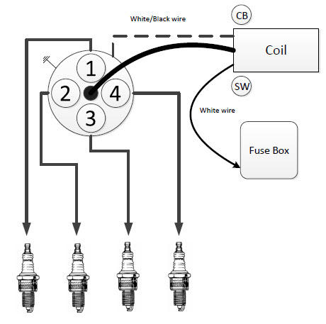
LT1 POWER MODULE WIRING DIAGRAM AND INSRUCTIONS Positive Voltage (B + ) PCM IGN Fuse 13 439 0220 439 S132 439 Hot In Run, Bulb Test And Start I Block Fuse Block Details Cell 11 power Distribuüon Cell 10 I ORN c 0.8 ORN 0.8 ORN PCM BAT Fuse 3 340 C210 340 Fuse Block Details Celi 11 0.8 PNK 439 Ignition Positive Voltage PCM Ground 0.8 PNK E 0.8 PNK 0.8 PNK 1-13 0.8 PNK S206 0.35 PNK 1 Instrument
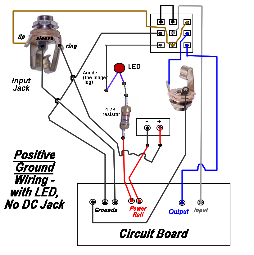
Rothstein Guitars • Serious Tone for the Serious Player
How To Test A Ground Wire For My Car Jan 25 2020 To check the ground you first have to see if the circuit has electricity on the positive side. 8 To test the wiring harness first remove the wires connected to the accessory. Take one of the probes of your tester and slide it into the larger slot on the outlet then insert the tip of the other probe into the small slot.
B.B. - 6 VOLT ELECTRICAL TIPS & TRICKS - The Flat-Spot
R Model 12 volt Positive Ground Wiring Diagram - Antique ... Description. R Model 12 volt Positive Ground Wiring Diagram. Here is a wiring diagram showing 12 volt positive ground for the old R & U Models... Followers 0.
Positive Earth Ignition wiring question : MGB & GT Forum : MG ...
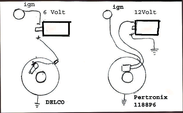
Pertronix Positive Ground Wiring - TTalk For Positive Ground Cars The wiring diagram shown below was obtained from Pertronix to show the proper hookup for a Pertronix Igniter in a car wired for positive ground, or earth if you prefer. It goes without saying that this is valid only for cars without ballast resistors, viz., our T-series cars. Correspondence from an engineer at Pertronix

6V System w/4 position switch w/cutout and Delco Remy ...
Tell me about 1 wire alternators and POSITIVE ground | The ... The only component that makes the alternator positive ground is the rectifier. The red jumper wire is connected between the (negative) "Bat" stud on the rectifier to the ground screw for the voltage regulator. The ring terminal on the red wire must contact the ground clip on the brush holder but be insulated from the screw.
install Pertronix ignitor : The 3000 Forum : Austin-Healey ...
Positive Ground Cars - Restore An Old Car Positive ground in automobiles was mostly abandoned with the introduction of 12-volt electrical systems in the fifties. 1955 was pretty much the last use of 6-volt electrics in American-made cars. Most cars switched from 6 volt positive ground to 12 volt negative ground together. One exception to this was the 1955 Packard, switching from 6v to ...
3010 john deere gas wiring | Green Tractor Talk
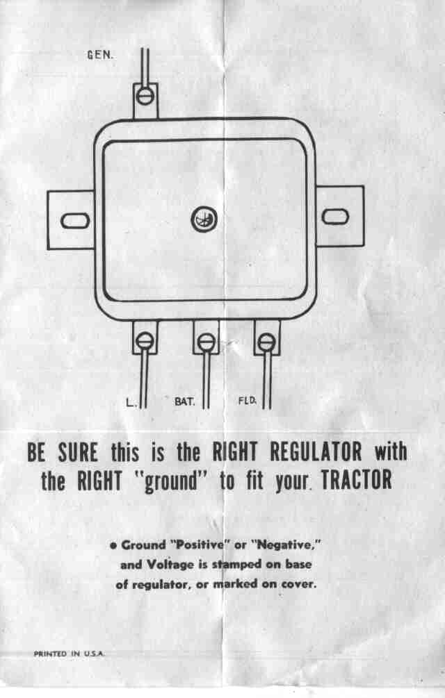
Wiring Diagram For 6v Tractor Voltage Regulator Positive ... Other than mounting the solenoid separate from the starter, the wiring is the same as the side-distributor 8N tractor. diagrams show the BEST way that I have found to convert your 6 Volt, Positive Ground, N-Series Tractor to 12 Volts, Negative Ground.A tractor's regulator takes the voltage provided by the battery, manages it by reducing it, and ...

Positive to Negative Ground Conversion
Wiring Diagram 6 Volt Positive Ground – Wiring Sample A positive ground system works by directly connecting the chassis of a vehicle to the positive side of the vehicles battery. Goes straight from the small terminal on the. Here is a picture gallery about 6 Volt Positive Ground Wiring Diagram complete with the description of the image please find the image you need.
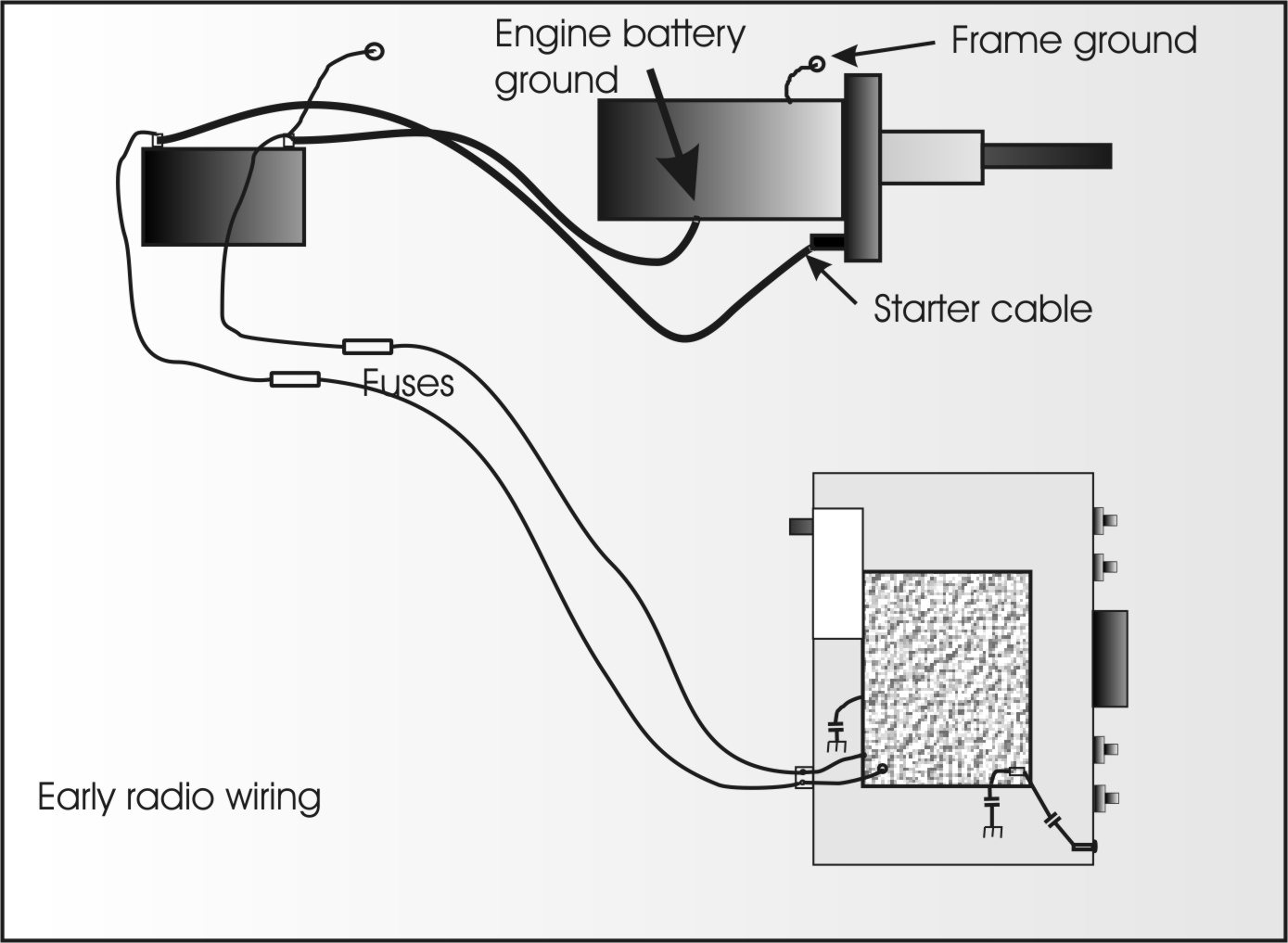
Mobile Radio Wiring and Grounding
200 Amp Disconnect Wiring Diagram Sample 2018-07-19 · To read a wiring diagram, first you have to find out what fundamental elements are included in a wiring diagram, and which pictorial symbols are utilized to represent them. The common elements in the wiring diagram are ground, power, wire and connection, output devices, switches, resistors, logic gate, lights, etc. A list of electrical symbols and descriptions …

Bob Johnstones Studebaker Resource Website (Studebakers ...
PDF 12-Volt Positive Ground Installation Instructions The Ignitor is designed for 12-Volt positive ground systems. 2. Leaving the ignition "ON" with the engine "OFF" for an extended period could result in permanent damage to the Ignitor. ... See figure "B" for wiring diagram. 2. Remove the ignition switch wire from the negative coil terminal. 3. Connect the ignition switch wire ...

Electric Start Wiring Diagram - Mud | Manualzz
Wiring Diagram For 6v Tractor Voltage Regulator Positive ... Wiring Diagram For 6v Tractor Voltage Regulator Positive Ground Solenoid Start 16.02.2019 3 Comments This walk-thru is based on the original 8N tractor 6 volt wiring. Many of those were later converted to the 8N type generator and voltage regulator, so this Two small screw terminals on the side of the generator are for "Ground" and " Field".
6v, 12v negative or positive ground? - Yesterday's Tractors
PDF Model a Ford Wiring - Mafca TYPICAL WIRING DIAGRAM (WITHOUT COWL LAMPS) beginning in February 1929. About Ford Wiring • Wires were cloth covered, rubber insulated • Ford used 16 gauge wire on lamp wiring ... 6V ground is Positive • Keep electrolyte levels correct - distilled water • Caps in place
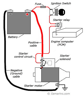
Starter motor, starting system: how it works, problems, testing
positive ground - Antique Tractors Forum 4,502 Posts. #3 · May 21, 2015. A couple of variables whether it's positive or negative ground. If it has the original generator on it then it should be positive ground. If it has been converted to an alternator then it will most likely be negative ground. The starter doesn't care which way it's hooked. J.
72 ford 2000 wiring positive post chasis grounded ...
Ford 6 Volt Positive Ground Wiring Diagram - U Wiring Oct 08, 2021 · The Five Wire Turn Switch Does Not Have The Brake Light Circuit And You Can Only Control The Flow Of Power To Each Rear Light Desc Diagram Turn Ons Stop Light. Introducing Pertronix 1285lsp6 6v Positive Ground Ignitor For Ford Flathead 8cylinder Get Your Car Parts Here And Follow Us For Ford Cylinder Tecumseh Engine.

Te20 generator and alternator wiring diagrams by Heads ...
Positive Ground Farmall H Wiring Diagram 6 Volt Collection Positive Ground Farmall H Wiring Diagram 6 Volt from usguidebook.comeluxitalia.it. Print the wiring diagram off and use highlighters in order to trace the signal. When you employ your finger or even stick to the circuit with your eyes, it’s easy to mistrace the circuit. One trick that We use is to print exactly the same wiring picture off twice.

Ground Activated Solenoids | Smith Co Electric
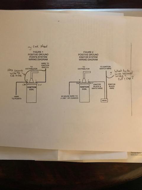
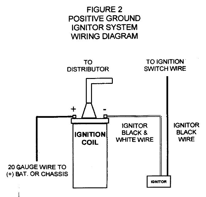
6-Volt Positive Ground Installation Instructions 1. See figure B for wiring diagram. 2. Remove the ignition switch wire from the negative coil terminal. 3. Connect the black Ignitor wire directly to the ignition switch wire. 4. Connect the Ignitor black/white wire to negative (-) side of the ignition coil. 5. Connect an insulated, AWG 20 copper stranded wire from the positive coil terminal to ...

Classic car Ignition
12v positive ground wiring question - Farmall Cub With the coil being correct for negative ground before and the wiring diagram from the GSS-1411 76 revised service manual seems to match my tractor exactly. The ground wire to the battery is red and the wire to the tractor is black, looks like someone just put the battery in wrong. Glad to hear it hasn't hurt anything.
Positive ground Fuzz Face offboard wiring clarification needed.
How To Ford F150 Stereo Wiring Diagram - My Pro Street 2016-02-02 · Left Rear Speaker Positive Wire (+): Orange/Light Green Left Rear Speaker Negative Wire (-): Light Blue/White Right Rear Speaker Positive Wire (+): Orange/Red Right Rear Speaker Negative Wire (-): Brown/Pink. This F150 is the last truck to use the bench style dashboard, and it’s a single DIN style stereo that installs right into the truck. Tenth generation …
1965 T120 Custom Wiring - No Battery | Triumph Rat Motorcycle ...
6volt positive ground question? - Technical - Antique ... With a positive ground system, the polarity is reversed from a negative ground system. In other words, the flow of electrons goes in the other direction. To get the polarity of the coil correct, the positive side of the coil goes to the points and the negetive side goes to the ignition switch. A distributor is divided in to two different ...
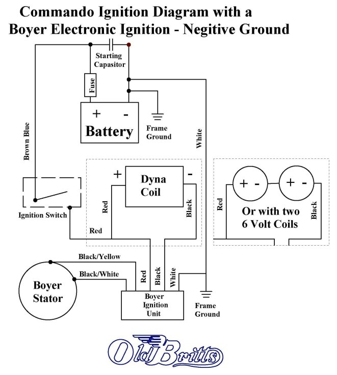
Old Britts, Simplified Wiring Diagrams
How To Wire Fog And Driving Lights Harness Wiring Diagram Consult your local and state regulations regarding minimum and maximum mounting height above the ground or specific lighting requirements. Harness Wiring. Note: This is a general wiring diagram for automotive applications. Use as reference only. Your lamp kit harness my have different wire colors. Locate the low beam or high beam light lead on one headlamp by using a …
IH Farmall Super A 6 Volt Positive Ground Generator & Regulator Install
How to Wire A Positive Ground One Wire Alternator ... Connect the one wire off the post on the new positive ground alternator with a 10 gauge wire to the top terminal of the ammeter as shown on your diagram. As I said in other replies if your electronic ignition was connected per the manufacturer and the tractor ran fine as you stated several times keep it connected as before and enjoy.
How to Convert Any 6-Volt Vehicle to 12-Volt
PedalParts.co.uk

wiring diagram generator - AllisChalmers Forum
98 Prostar Engine Wiring for Pertronixs Distributor - TeamTalk

6V Starting and Charging Issues on 1954 Windsor - Chrysler ...
1950 Farmall Cub
Bob Johnstones Studebaker Resource Website (Wiring Diagram ...
6 Volt Generator "TO" 6 Volt Alternator Conversion, Farmall M ...
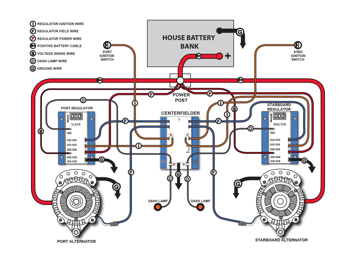
Centerfielder II - BalmarBalmar

coil hookup with + ground - Technical - Antique Automobile ...
I'm a newbie wishing to know what I have. (2013) | Page 9 ...

Smith Brothers Services - Sealed Beam Plow Light Wiring Diagram

53 case vac tractor converting to 12th negative ground

WIRING DIAGRAM FOR FREQUENCY METER (602-1472) POSITIVE GROUND ...

Positive ground vs Negative Ground - Which manual is correct ...

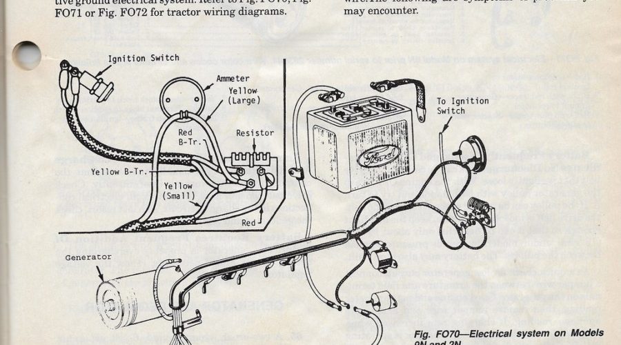
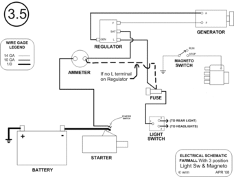
WIRING DIAGRAMS
Technical - Changing '46 Dodge truck to 12V neg ground - Coil ...

Hot-Spark, ignition products. Installation instructions

Electronic Ignition Conversion | PerTronix 1247P6 Ignitor ...
Sports Coil polarity - The 'E' Type Forum


Comments
Post a Comment