41 led dimmer circuit diagram
12V LED Dimmer Circuit - ElectroSchematics.com The occasion for this project was retrofitting an illuminated wall picture with LED backlighting. As soon as I applied LED power, the brightness blinded me — much brighter than the original T20 fluorescent tube, so I knew immediately that a dimmer control was required. Schematic of the LED Brightness Control Circuit. LEDs strip 2 Way Led Dimmer Switch Wiring Diagram - U Wiring 3 Way Dimmer Switch Wiring Diagram In 2021 Lamp Switch Touch Lamp Light Switch Wiring . Apnt 2 2 Way Lighting Guide With Fibaro Dimmers Vesternet Dimmer Lighting Guide Home Automation . Single Dimmer Switch Wiring Diagram Dimmer Switch Dimmer Led Dimmer Switch . Leviton Light Switch Wiring Diagram Single Pole Decora With Dimmer For 3 Way Switch ...
Dimmer Diagram - easywiring In the diagram below a 2-wire NM cable supplies power from the panel to the dimmer boxThe black line wire connects to the common terminal of the 3-way dimmerA 3-wire NM connects the travelers of the dimmer to the travelers of the 3-way switchTraveler wires are interchangeable on each switch.

Led dimmer circuit diagram
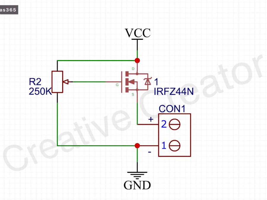
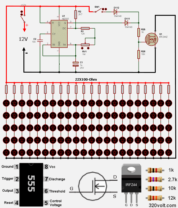
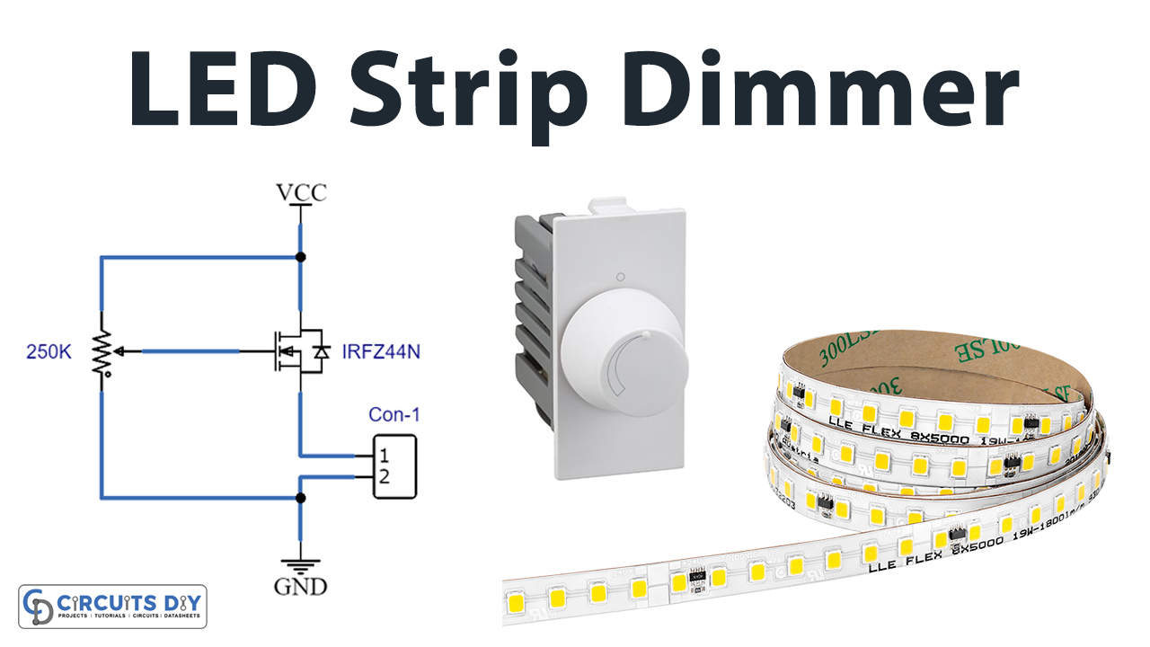
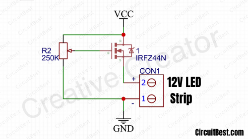
PWM LED Dimmer Circuit | Brightness Control by 555 Timer ... This one is called PWM LED dimmer circuit. The main idea is- by changing the pulse width of a square wave, it is possible to control the brightness of the LED. We have a distinct discussion on the PWM signal generation. Here NE555 timer IC is used to produce the PWM signal. Led Dimmer Circuit Schematic LED Dimmer Circuit Using LM317 Voltage Regulator IC A LED Dimmer is a circuit that works with light fixtures to control the brightness of a light. By changing the voltage waveform being applied to the lamp or LED, it is possible to lower the intensity of the light output.Although variable-voltage devices are used for various purposes, the term dimmer is generally for those electronic circuits intended to control light output; from resistive ... LED Dimmer Circuit with IRFZ44N MOSFET - circuits-diy.com Circuit Diagram Working Explanation In this LED Dimmer Circuit with IRFZ44N MOSFET, the MOSFET is only connected with two components, the potentiometer, and the 12V LED strip. As we know MOSFET has three pins, Source, drain, and gate. The potentiometer is connected with the gate and its rotation changes the gate voltage.
Led dimmer circuit diagram. The simplest led dimmer circuit diagram - YouTube This easy electronic project is the simplest led dimmer that works well and uses minimum electronic components as possible the circuit consumes very low ener... Fabulous Led Dimmer Switch Wiring Diagram Of Synchronous Motor Simple and easy to understand video on how to safely wire a dimmer switch. Led dimmer switch wiring. Then remove the bezel and unscrew the mounting. The process of installing a dimmer switch for led is the same as that of installing a switch. Ist diese dimmbar müssen sie wie oben darauf achten dass auch der dimmer. LED Dimmer Circuit with 555 Timer - circuits-diy.com Circuit Diagram Working Explanation In this LED Dimmer Circuit, 555 timer works as an astable multivibrator, generates PWM pulses. The circuit includes the timing components like Resistors, potentiometer, and capacitor Thus, the potentiometer is there to adjust the duty cycle of the PWM signal. How to Add a Dimmer Facility to a LED Bulb - Homemade ... However, the dimming effect can be perhaps implemented by connecting the series LED section of the LED bulb with the IC 555 circuit, as indicated in the following diagram: We know that an LED bulb circuit is nothing but a small AC to DC SMPS circuit, which employs a small ferrite transformer for stepping down the mains voltage to a lower LED DC ...
Led Dimmer Switch Wiring Diagram - Diagram Sketch Led Dimmer Switch Wiring Diagram. angelo on September 29, 2021. Pin By Eric Higginson On Diy Projects Dimmer Switch 3 Way Switch Wiring Led Dimmer Switch . Unique Light Fixture Wire Diagram Diagram Wiringdiagram Diagramming Diagram Visuals Led Fluorescent Tube Fluorescent Tube Unique Light Fixtures . 5V LED Dimmer Circuit - ElectroSchematics.com This is a very simple LED dimmer circuit which has 2 transistors, 1 resistor and 2 potentiometers. Typical segment displays LEDs consume around 25 mA for each segment and should be limited to this value by using resistors. If a six digit display is to be current limited, at least 42 series resistors are needed. PDF 0-10V dimming wiring diagram - Crenshaw Lighting Crenshaw LED Lutron 3-wire LED dimming wiring diagram Lutron 3-wire LED dimmer switch switched hot (black ) Electrical Panel hot (black) 120V/277V ground ground dimmed hot (orange) LED pendant, sconce, or ceiling Lutron Hi-Lume A 1% L3D series Lutron 103P (120V) Lutron 103P-277 (277V) or other Lutron compatible controls switch load limits apply ... PWM LED Dimmer Using NE555 - circuit-diagramz.com Circuit Diagram of PWM LED Dimmer Using 555 Components Required 555 Timer IC 1KΩ Resistor x 6 Red LEDs x 4 2N2222 NPN Transistor 0.1μF Capacitor 0.01μF Capacitor 50KΩ Potentiometer 1N4148 Diodes 12V Power Supply Mini Breadboard Circuit Design The 12V DC supply is given to the VCC Pin for operating voltage of 555 timer.
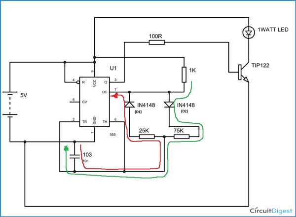
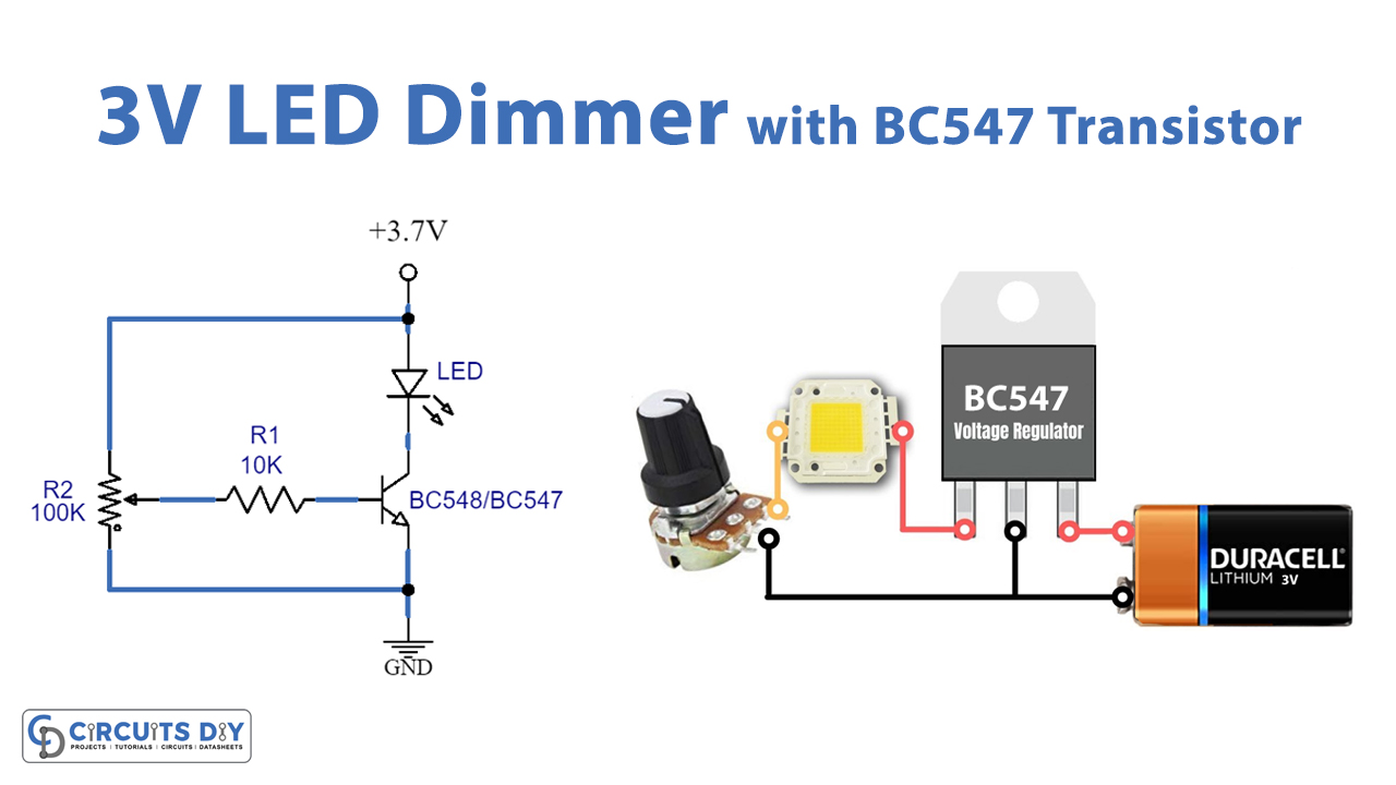
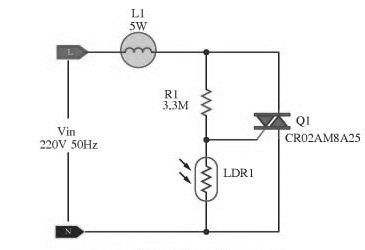
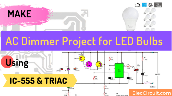
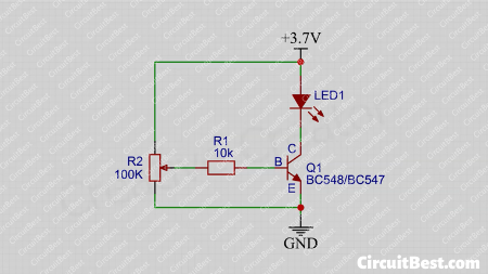
Dimmer circuit using SCR - TRIAC - ElecCircuit.com Since the general dimmer uses TRIAC to control a load like a relay contact. So we can easily make it by a few parts. See Figure 1. We put the parts includes S2, LDR, and RA-33K, 1/2W or RB to the AC dimmer circuit. Turn-on a switch-S2, this circuit becomes the automatic light switch circuit. 1 Watt LED Dimmer Circuit - circuits-diy.com Hardware Component s The hardware components required to make 1 Watt LED Dimmer Circuit are: Circuit Diagram Circuit Operation All PWM generation occurs due to the variations in the charge and discharge times of the device's capacitor. Remember now that the pot is adjusted, and the resistance split into 25 K on one side and 75 K on the other. Basic LED Dimmer : 5 Steps (with Pictures) - Instructables Basic LED Dimmer: In this Instructable you will learn how to build a simple LED dimmer using just a potentiometer. The Arduino kit that I'm using was kindly provided by Kuman (kumantech.com). You can find it here. 3V LED Dimmer Circuit with BC547 Transistor Circuit Diagram Working Explanation In this 3V LED Dimmer Circuit with BC547 Transistor, the transistor is only connected with two major components, the potentiometer, and the output LED. Basically, the transistor has 3 pins. The potentiometer is wired with the base of the transistor therefore its rotation changes the base voltage.
Ace Led Dimmer Switch Wiring Diagram 3 Phase Immersion Heater Led wall dimmer switch wiring diagram effectively read a wiring diagram one has to find out how typically the components within the method operate. When you use your finger or the actual circuit along with your eyes it s easy to mistrace the circuit. Advice and wiring instructions for fitting or installing a dimmer light switch.
Making a Simple LED dimmer #leds #circuits #jandroverse ... About Press Copyright Contact us Creators Advertise Developers Terms Privacy Policy & Safety How YouTube works Test new features Press Copyright Contact us Creators ...
LED Dimmer Circuit- A Beginners Guide - ourpcb.com 7 simple LED dimming circuits . There are several types of LED dimming circuits. Among the key ones include the following: Simple LED Dimmer Circuits . Figure 3: Simple LEDs . You can dim a LED by constructing a simple dimming circuit. All you need to have is a simple circuit comprising a power source, a dimmable LED lamp, and a potentiometer.
PDF LED Dimming: What you need to know - Energy • Dimming an LED source can change the behavior of the Driver • LED dimming performance is determined by Driver capability and compatibility with the dimming equipment • Multiple compatibility issues are rooted in circuit level interactions between the LED Driver and dimmer • What you think you know may no longer be valid
Sensational Light Dimmer Circuit Diagram Motor Esc Connection Working of led lamp dimmer circuit. Led are available in many colors like red orange amber yellow green blue and white. It causes l1 is more brightest. The capacitor c2 in the circuit below gets charge from the main supply. The irfz44n is an n channel enhancement type mosfet to it can deliver high output for a simple led dimmer.
LED dimming basics for low-voltage LED lighting Typical wiring diagram when using a 120-volt AC dimmer Large lighting applications may require the use of multiple dimmable LED drivers/power supplies. For synchronized on/off and brightness control of LED lighting on multiple power supplies, connect a 120-volt AC dimmer to multiple Armacost Lighting Dimmable LED Drivers .
Amazing Leviton 3 Way Led Dimmer Switch Wiring Diagram ... This 3 way dimmer switch is wired as follows. Leviton 3 way switch wiring diagram leviton 3 way dimmer switch wiring diagram leviton 3 way led dimmer switch wiring diagram leviton 3 way light switch wiring diagram every electrical structure is composed of various distinct parts. Wellborn collection of leviton three way dimmer switch wiring diagram.
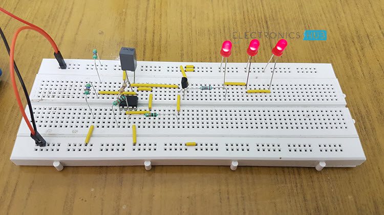
PWM LED Dimmer Circuit Diagram using IC 555 Timer Circuit Diagram The circuit is connected in breadboard as per the circuit diagram shown above. However one must pay attention during connecting the LED terminals and the transistor ones. If the LED does seen to flicker at any stage replace the capacitor with a lower capacitance one.
LED Lamp Dimmer Circuit You can also build this circuit with high-power LEDs for real-time use by making minor changes to the power dissipation. LED Lamp Dimmer Circuit Diagram Circuit Components IC LM358 (IC1) - 1 Transistor BC547 (T1) - 1 Resistors (R1, R2) 4.7KΩ - 2 Resistor (R3) 22KΩ - 1 Resistor (R4) 10KΩ - 1 Resistor (R5) 4.7MΩ - 1 Resistor (R6) 100Ω - 1
LED DIMMER WITH CIRCUIT DIAGRAM - Blogger LED DIMMER WITH CIRCUIT DIAGRAM February 05, 2014 In this circuit, at the starting LED glow slowly, then grown brighter and once again slowly it became dim. The basis of the whole circuit is an operational amplifier IC named LM358. Circuit Diagram of LED Lamp Dimmer:
LED Dimmer and DC Motor Speed Controller Circuit Using PWM ... Circuit Diagram. Below is the circuit diagram of PWM controlled LED Dimmer circuit: If you wish to control heavy loads like DC Motors or LED strips, you need to connect a mosfet to the output of 555 timer IC and connect motor / LED strip to the drain pin of mosfet. Below circuit showcases that arrangement: How This Circuit Works
LED Dimmer Circuit with IRFZ44N MOSFET - circuits-diy.com Circuit Diagram Working Explanation In this LED Dimmer Circuit with IRFZ44N MOSFET, the MOSFET is only connected with two components, the potentiometer, and the 12V LED strip. As we know MOSFET has three pins, Source, drain, and gate. The potentiometer is connected with the gate and its rotation changes the gate voltage.
LED Dimmer Circuit Using LM317 Voltage Regulator IC A LED Dimmer is a circuit that works with light fixtures to control the brightness of a light. By changing the voltage waveform being applied to the lamp or LED, it is possible to lower the intensity of the light output.Although variable-voltage devices are used for various purposes, the term dimmer is generally for those electronic circuits intended to control light output; from resistive ...
PWM LED Dimmer Circuit | Brightness Control by 555 Timer ... This one is called PWM LED dimmer circuit. The main idea is- by changing the pulse width of a square wave, it is possible to control the brightness of the LED. We have a distinct discussion on the PWM signal generation. Here NE555 timer IC is used to produce the PWM signal. Led Dimmer Circuit Schematic

















Comments
Post a Comment