39 brake plumbing diagram
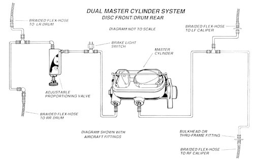
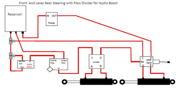
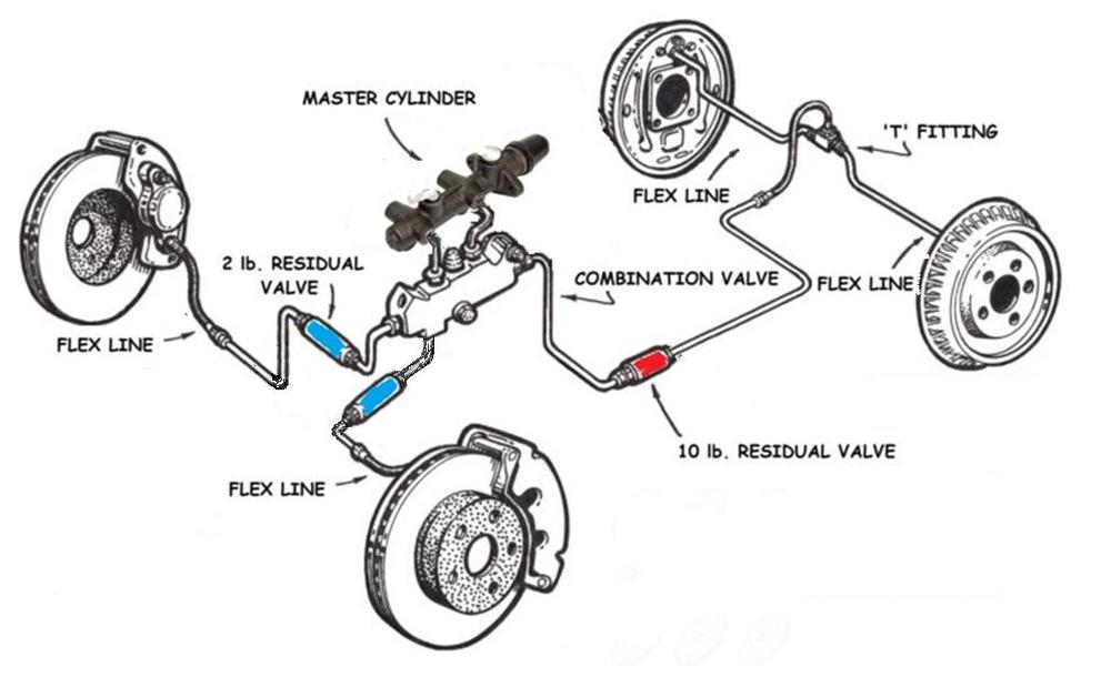
Brake System Diagram - Street Rod - Speedway Motors This diagram shows a typical street rod brake system. A 2 PSI residual pressure valve (RPV) is needed in the disc brake circuit, and a 10 PSI RPV is required in the drum brake circuit as well as an adjustable proportioning valve (APV). This diagram illustrates the 2 most common types of fittings used in street rod brake systems. Steering Gear Plumbing Diagram With & Without Hydro Boost Contact Us. Lee Power Steering. 28259 Constellation Road. Santa Clarita, CA 91355. Phone: 661-568-9170. Fax: 661-885-8185. Email: info@leepowersteering.com
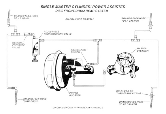
Brake Line Kit Plumbing Diagram - Classic Perform Brake Line Kit Plumbing Diagram INSTALLATION NOTES: On Disc front, Drum rear combinations with a single master cylinder, be sure to remove the residual check valve, or purchase a master cylinder without a check valve.

Brake plumbing diagram
All wheel disc brake plumbing diagram? | Vintage Mustang ... 1) brake failure switch: basically a shuttle that senses a pressure differential between the two brake systems. It does NOT shut off a failed system. This is the same for drum/drum, disc/drum, or disc/disc systems. 2) Metering valve. This valve delays the front brake activation slightly to lessen the nose dive effect. Dual Master Cylinder plumbing - Classic Parts Talk Jun 8, 2012. Messages: 57. Location: S Indiana. I am installing a new dual master cylinder from Classic. After mounting the cylinder, does it matter which port goes to front or rear brake lines. Something is telling me that the forward most port goes to the rear brakes since the cylinder is mounted push rod forward. Brake line diagram - Hot Rod Forum Brake line diagram. Jump to Latest Follow 1 - 7 of 7 Posts. Longboard · Registered. Joined Feb 28, 2004 · 157 Posts . Discussion Starter · #1 · Mar 20, 2010 (Edited) Only show this user ...
Brake plumbing diagram. Cutting Brake plumbing | Pirate 4x4 push down the brake pedal approx 7/8 travel and then push and hold the cutting brake lever at about 7/8 travel. close the bleeder but continue to hold the cutting brake. release the pedal but not the cutting brake. pump the pedal slowly, allowing the cutting brake to return but with hand pressure against it. How To Build A Custom Brake Plumbing System for Classic or ... is a long one so grab a beverage and hunker in for a bit because we get a lot done on the Autoedit Ford Mustan... PDF TECHNICAL - Classic Perform 4 Wheel Disc Brakes Plumbing Diagram . .335 500 Series™ Power Steering Box Comparison . .351 Axle Measurements . .343 Big Brake Template . .337 Bolt Pattern Circle Template . .329 Brake Booster Assembly with Slave Cylinder . .335 Brake Booster Details . .336 Brake Hose Installation Tip . .331 Chevy Truck Rear End Info . PDF ALUMINUM TANDEM MASTER CYLINDER - Wilwood Disc Brakes Plumbing Notes and Precautions • Each master cylinder kit includes one 9/16-18, one 1/2-20, and two 3/8-24 inverted flare threaded line adapters for connections to the brake lines (Adapters are not installed and are shipped in the reservoir of the master cylinder, remove lid to access).
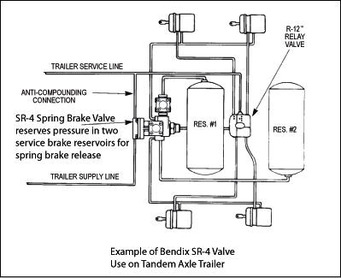
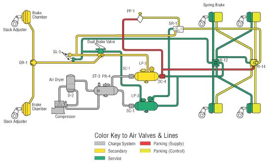
Brake Plumbing - ecklerscorvette.com Brake Plumbing. The ABCs of brake line plumbing, and what you need to haul that Ford down. A disc brake upgrade and dual master cylinder upgrade are some of the most common discussions amongst Ford owners. The most misunderstood ingredient of these swaps is distributing the brake fluid out to each wheel. When upgrading the brake system, it can ... Piping diagrams: spring brake control for trucks - St ... St. Louis Truck Driveshafts, Suspensions, Brakes 314-231-5047 Spring Brake Controls for Trucks - Piping Examples The most basic spring brake control function are "quick release" and "anti-compounding". The illustration at the right shows how a Bendix QR-1C accomplishes both of these functions with an important link to the service relay circuit. PDF Air Brake Plumbing, Cab Diagram 42 - JustAnswer Air Brake Plumbing, Cab Diagram 42 See Fig. 1 for a full view of the air brake plumbing (cab) diagram. See Fig. 2 or Fig. 3 for partial (de- tailed) views of this diagram. 01/16/96 f421408 Diagram 680 429 02 B1, Rev. Ltr. H Fig. 3 Figs. 2 & 3 Fig. 2 Fig.1, Cab Air Brake Plumbing Diagram Air Brake Plumbing, Cab Diagram42.00 Cab Diagram Piping diagrams: spring brake control for trailers - St ... Bendix SR-5 The current technology in trailer spring (emergency) brake control is a valve that can safely manage the supply of air for service and parking brakes using just a single large reservoir. Bendix SR-5 valve uses air pressure from the trailer supply line rather than from any reservoir in this two reservoir example.
PDF Meritor WABCO Air Brake Systems Workbook The purpose of an air brake system on heavy duty vehicles is to convert air pressure to mechanical energy to activate the foundation brakes. Federal Motor Vehicle Safety Standard 121 dictates how this is to be done for over-the-road vehicles. The purpose of this book is to help you construct Meritor WABCO Truck and Tractor air systems. Brake Line Kit Plumbing Diagram - Zig's Street Rods Brake Line Kit Plumbing Diagram INSTALLATION NOTES: On Disc front, Drum rear combinations with a single master cylinder, be sure to remove the residual check valve, or purchase a master cylinder without a check valve. Brake Plumbing - Ecklers Automotive There are many types of combination valves, this discussion will refer to the typical combination valve used in 1970 - 1980 Ford vehicles using front disc brakes and rear drum brakes. The Ford combination valve has three to four functions: 1. Fluid distribution - Typical Ford master cylinders have two outlets, while the vehicle has four wheels. PDF Air Brake Handbook - suspensionspecialists.com the foot brake valve moves, opening channels within the valve that allow the air pressure waiting there to pass through and be delivered to the rear and front brake systems. The pressure quickly increases in the brake chambers and applies force to the push rod, transferring the force to the SCam or air disc brake.
Plumbing Trailer Brake Hand Valve - HDT - Escapees Discussion ...
Basic Air Brake System Schematics - Total Truck Parts Basic Air Brake System Schematics Typical 6 Wheel Air Brake System These diagrams are provided for basic identification only. Always consult a professional technician to properly troubleshoot your system. Typical 10 Wheel Brake System These diagrams are provided for basic identification only.

Everything You Need to Know About Converting Drum Brakes to Disc
Air plumbing diagram for a B75? - Air Systems and Brakes ... Now I need to figure out where to plumb all the air lines, including all the stuff under the dash, i.e. windshield wiper, front air brake, trailer brake, etc. Where can I find a good schematic diagram that will show me how to plumb these lines. I was really surprised that the windshield wiper motor had like 4 or 5 air lines going in and out of it.

Technical - Brake Plumbing Question | The H.A.M.B.
PDF Instructions For Vacuum Reserve System - Jegs High Performance Refer to the hookup diagram below. 2. Securely mount the tank in a convenient location, under the ... mounting the tank. 3. Remove the power brake vacuum hose from the engine and the brake booster.Install a new vacuum hose from the same engine vacuum source to the plastic check-valve on the tank. Make sure that you use power brake type vacuum ...

34321022150 MINI Cooper Replacement Brake Pipe Bracket - MINI ...
Brake Line Kit Plumbing Diagram - installs.hartrods.com Brake Line Kit Plumbing Diagram INSTALLATION NOTES: On Disc front, Drum rear combinations with a single master cylinder, be sure to remove the residual check valve, or purchase a master cylinder without a check valve.
Hydraulic brake - Wikipedia
PDF Air Brake System Troubleshooting -Brakes need adjusting or lubricating.-Low air pressure in the brake system (below 60 psi).-Insufficient brake valve delivery pressure.-Excessive leakage with brakes applied.-Restricted tubing or hose.-Treadle travel restricted.-If remote mounted brake valve, check linkage. 3.) Brakes Release Too Slowly-Brakes need adjusting or lubricating.
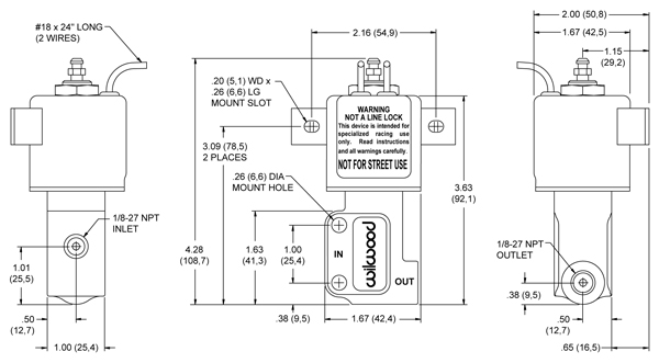
Wilwood Disc Brakes - Porportioning Valves & Pressure Valves
Designing Your Brake System - How To Build Hotrods It sets front to rear braking ratio. That is, it lets the front brakes have a little more pressure than the rears. This is to make the brakes stop at the same time, with the fronts locking up just ahead of the rears. Your front brakes do most of the stopping. 3. It does the job of a RESIDUAL PRESSURE VALVE. It keeps 10 PSI in the drum brake lines.
Brake Line Kit Plumbing Diagram
PDF PV2/PV4 Proportioning Valve KIT Installation Instructions Install lines as shown in diagram: The most common proportioning valve plumbing is shown. An alternative plumbing method is to plug off the top front line and have the bottom front line go to a "T" fitting. From the "T" fitting, the front lines are then PV2 cutaway Shown split off to the left and right calipers.

Putting air brakes on trailer | The Farming Forum
Brake Plumbing Basics with Speedway Motors - YouTube If you have the horsepower, you should also have the brake power! Here is an overview of the differences in brake lines, flare types and fittings you may wan...
Original Parts for E36 320i M50 Cabrio / Brakes/ Brake Pipe ...
Brake System Fabrication - Hot Rod Brake Basics A few more measurements, marks, and bends and the final piece of hard line is formed and run from the left front line junction to the right side connection with the braided flex line to the left...
Piping diagrams: spring brake control for trailers - St ...
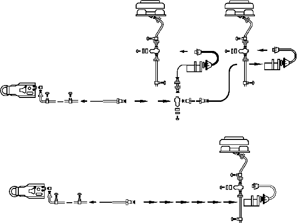
PDF AIR SYSTEM PIPING DIAGRAMS Pre-121 Trailer Air Systems AIR SYSTEM PIPING DIAGRAMS 121 Trailer Air Systems Tandem Axle Trailer (Spring Brake Priority 110500 or 110800 / Service Reservoir Priority 110700) Tandem Axle Trailer (Protected Reservoir System) Phone (602) 253-1007 Page 72 Fax (800) 222-2334
Trailer Parts Superstore - Brake Line Diagram
Brake line diagram - Hot Rod Forum Brake line diagram. Jump to Latest Follow 1 - 7 of 7 Posts. Longboard · Registered. Joined Feb 28, 2004 · 157 Posts . Discussion Starter · #1 · Mar 20, 2010 (Edited) Only show this user ...
Brake Plumbing
Dual Master Cylinder plumbing - Classic Parts Talk Jun 8, 2012. Messages: 57. Location: S Indiana. I am installing a new dual master cylinder from Classic. After mounting the cylinder, does it matter which port goes to front or rear brake lines. Something is telling me that the forward most port goes to the rear brakes since the cylinder is mounted push rod forward.
Plumbing Diagrams - Scotts Custom Off Road
All wheel disc brake plumbing diagram? | Vintage Mustang ... 1) brake failure switch: basically a shuttle that senses a pressure differential between the two brake systems. It does NOT shut off a failed system. This is the same for drum/drum, disc/drum, or disc/disc systems. 2) Metering valve. This valve delays the front brake activation slightly to lessen the nose dive effect.

Step 39b: Plumbing — Stop it! | wrenchingseason
Master cylinder brake line plumbing | Jeep Wrangler Forum
Basic Air Brake System Schematics
Brake line plumbing for 4 wheel disc brakes | Team Chevelle
Brake Master Cylinder Brackets – Cheerful Curmudgeon
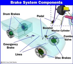
How Brakes Work | HowStuffWorks
Brake Line Kit Plumbing Diagram

Brake Plumbing
BODY BUILDER INSTRUCTIONS

Brake System Diagram - Street Rod
67 Brake Diagram Request | StangNet

ONE PIECE HYDRAULIC DISC BRAKE CALIPER WITH ONE WAY PLUMBING ...
Brake Combination Valve | SpeedsterOwners.com - 356 ...
Land Rover Defender 110 Brake Lines | Rovers North - Land ...

Selecting And Installing Brake System Components: Proper ...
Brake line diagram | Hot Rod Forum
Wilwood Rear Superlite 4R Brake System - Ridetech

Dual-circuit air system - SGI

Brake Residual Valve Location Help - The 1947 - Present ...

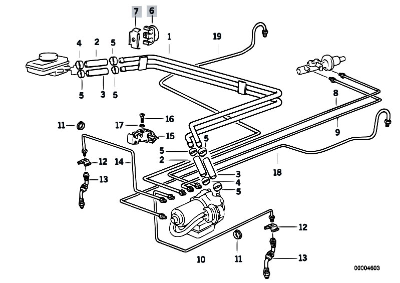
RealOEM.com - Online BMW Parts Catalog
Sealco Commercial Vehicle Products - Air System Piping Diagrams

HydroBoost Plumbing Diagram Help - The 1947 - Present ...

Automotive Brake System Drawings - Ted's Modeling Marketplace
Master Cylinder Assembly - Diagram View - Chicago Corvette Supply
Technical - Ford brake proportioning block plumbing | The ...
Rover Mini Brake Pipes and Fittings | Rimmer Bros


Comments
Post a Comment