43 brushless motor winding diagram
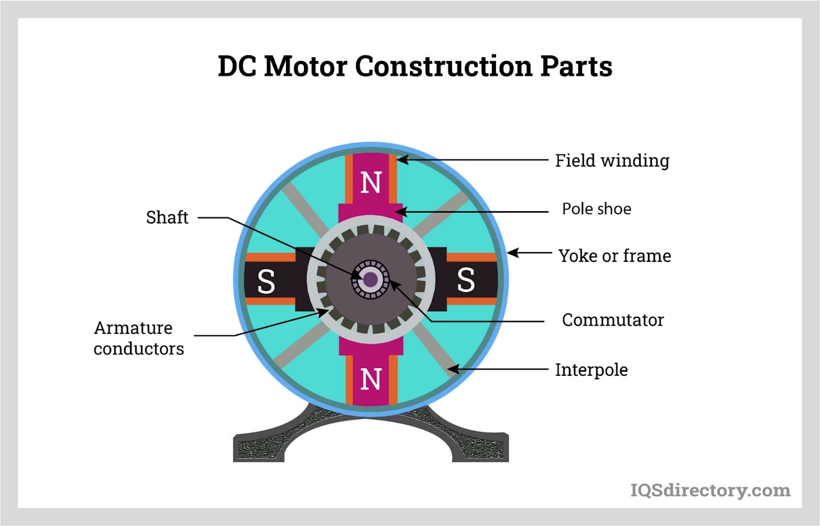
Rewinding a 2205 Brushless Motor | Elettronica, Progetti Brushless Dc Motor Winding Diagram Simple Electronics, Electronics Components, Electronics Projects, Electronic Schematics. Mark A.Kopecki. 14 followers. 3 Phase Motor Winding Diagram & Resistance Values If it's a DC Motor, assess the brushes. There should be 3-4 round caps to remove around the motor. Under these, you will discover spring with a square block (brush). See just how much is left perhaps need to replace. Also, assess the commutator that the brushes ride for wear; try wiping the surface down. 3 Phase Motor Winding Connections
Brushless Motor Wiring Diagram | Diagrama de circuito ... Brushless Motor Wiring Diagram Electrical Engineering Books, Electrical Projects, ... Motor winding diagram -- star connection Electrical Diagram.

Brushless motor winding diagram
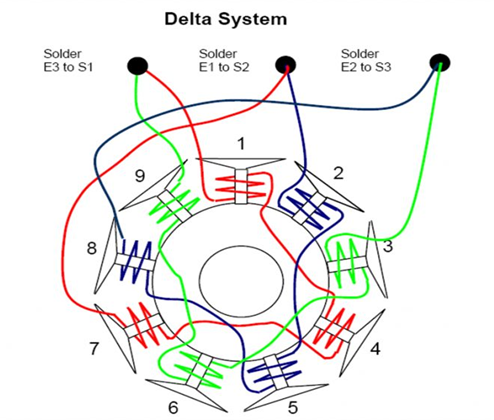
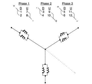
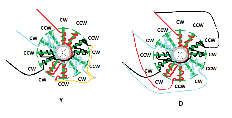
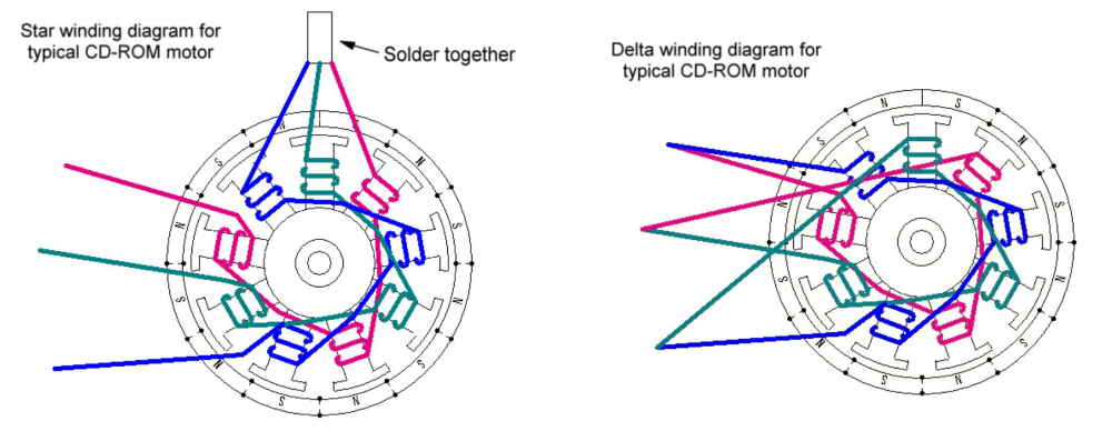
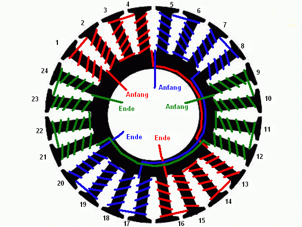
All about RC Brushless Motor Windings - Radio control Feb 03, 2019 · There are two wiring patterns to terminate the windings on a brushless motor. One termination method is known as the Wye wind. The other termination method is known as the Delta wind. In a Wye wind, each motor connector is attached to the start of a phase. All three legs or loads are terminated together as below in the top diagram. PDF Brushless DC Motors - engineering.nyu.edu Elementary Two-Pole, Single-Phase Stator Winding Actuators & Sensors in Mechatronics: Brushless DC Motors K. Craig 8 – Now, consider the diagram of the elementary two-pole, two-phase stator windings. Here we have added a second winding – the bs winding. – The magnetic axis of the bswinding is displaced ½ π from that of the aswinding. [No. 13] Winding diagram for an AC motor | Simulation ... [No. 13] Winding diagram for an AC motor Last modified at 2 Sep 2019 Here we see a winding diagram for a 3-phase AC induction motor or brushless PM motor (IPM), having 4 poles and 36 slots. This winding could in fact be used with any AC machine, including a synchronous reluctance motor or a wound-field synchronous motor or generator.
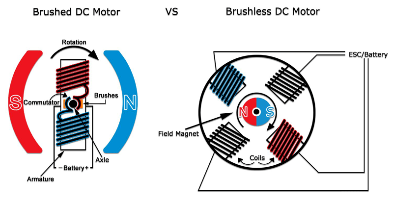
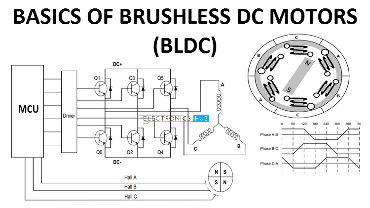
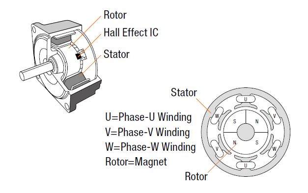
Brushless motor winding diagram. PDF AN885, Brushless DC (BLDC) Motor Fundamentals The stator of a BLDC motor consists of stacked steel laminations with windings placed in the slots that are axially cut along the inner periphery (as shown in Figure 3). Traditionally, the stator resembles that of an induction motor; however, the windings are distributed in a different manner. Motor Winding Connection Diagram» All Motor Winding ... 4 wire motor connection diagram-by motorcoilwindingdata.com Three Wire Motor Winding Connection Diagram. In a 3-wire motor, three wires are drawn out from the winding of the motor. Among these, one wire is COMMON WIRE and the other wire is of the running winding, and the third wire is drawn in the starting winding. PDF Brushless DC Motor Control Made Easy A brushless motor is constructed with a per- ... the wound stator poles. FIGURE 1: SIMPLIFIED BLDC MOTOR DIAGRAMS Author: Ward Brown Microchip Technology Inc. N S A C a a b b c c B com com com N N S S 110 010 011 101 100 001 N S S N 6 3 4 1 2 5 A C B c b a com Brushless DC Motor Control Made Easy. ... mutate the winding currents is by means of ... What is a brushless motor and how does it work? The windings on a brushed motor are located on the rotor whereas they are located on the stator in the brushless motor. By positioning the windings on the stator or the stationary part of the motor, the need for brushes can be eliminated. In a nutshell, the main difference between a brushless motor and a brushed motor is that instead of ...
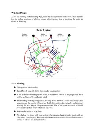
Brushless DC Motors - Part I: Construction and Operating ... Brushless DC Motors - Part I: Construction and Operating Principles. February 11, 2013. by Pushek Madaan, Cypress Semiconductor. Comments 15. Electrical equipment often has at least one motor used to rotate or displace an object from its initial position. There are a variety of motor types available in the market, including induction motors ... How to Power and Control Brushless DC Motors | DigiKey A sensorless BLDC motor makes use of the electromotive force (EMF) that gives rise to a current in the windings of any DC motor with a magnetic field that opposes the original change in magnetic flux as described by Lenz's Law. The EMF tends to resist the rotation of the motor and is therefore referred to as "back" EMF. DIY Winding a Brushless BLDC 12 kW Motor - YouTube You are looking for a big Brushless DC Motor for your Electric Car or Powered Paraglider? I show you how to make the winding. The Rotor and Stator parts I ha... Rewinding a Brushless Motor : 11 Steps (with Pictures) It is a Delta wound 8T (It means 8 turns) quad wind. The winding pattern described in this tutorial (called an ABC wind - ABCABCABC as you go around the stator) works for any brushless motor with 9 stator teeth and 6 magnets. Ask Question Step 2: Knowing Our Motor First, obviously you'll need to remove the old wires from the motor.
Motor winding diagram -- star connection | Electrical ... Muita gente tem-me perguntado como enrolar um motor Brushless, então resolvi postar aqui a minha experiência, embora apenas faça uma breve síntese, ... Brushless motor principle application advantage and diagram Brushless motor consists of mainly two parts; stator & rotor. The bldc motor stator consists of stacked steel laminations with windings placed in the slots that are axially cut along the inner periphery. Stator is made up of silicon steel stamping with slots. The slots accommodate in armature windings. Brushless DC Motor | Working Principle | Characteristics ... Brushless DC motor Circuit Diagram: Novotny-Abbas circuit model of a CSI fed Brushless DC Motors is drawn in Fig. 8.86. Currents (balanced) flowing in the synchronous machine of the brushless dc machine set up of Fig. 8.82 are rectangular pulses ac as shown in the wave forms of Fig. 8.83. Actual currents are somewhat rounded pulses. Design of a Three-Phase Brushless DC Motor Control System DESIGN OF A THREE-PHASE BRUSHLESS DC MOTOR CONTROL SYSTEM A Thesis presented to ... 2.2 Diagram of a Three-Phase Brushless DC Motor . . . . . . . . . . .6 ... In the brushed DC motor, current is carried to coil windings of the rotor via physical brushes, generating a rotor magnetic eld that varies in direction depending ...
Brushless Dc Motor Winding Diagram | Electrical projects ... Brushless Dc Motor Winding Diagram Electronic Engineering, Mechanical Engineering, Electrical Engineering, Chemical Engineering. Robertogoncalvesdeoliveira.
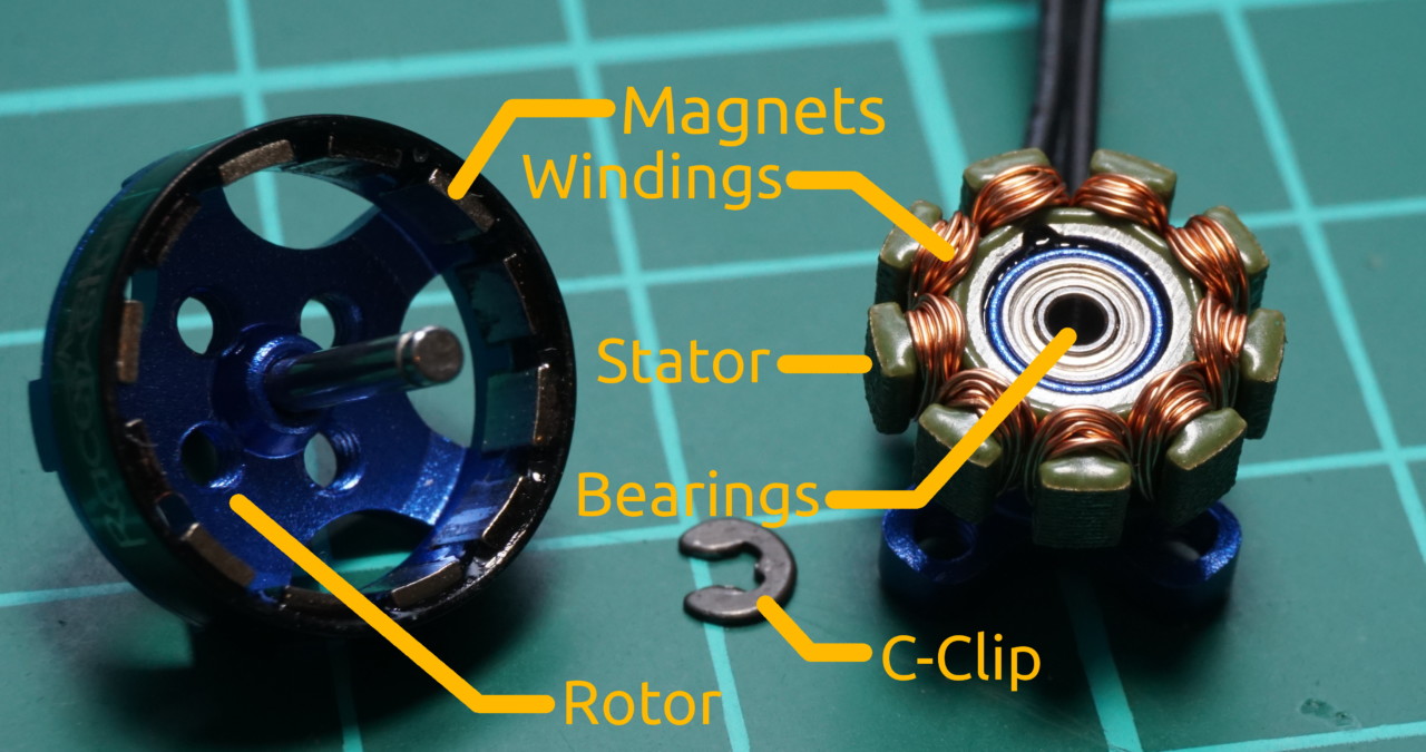
Tutorial: Brushless motor rewinding based on a BR1103B ... Nov 10, 2017 · The stator is made of thin metal sheets and several windings of copper wire form electromagnets that can create magnetic fields that can be controlled by your ESC. For three phase brushless motors, the number of stator poles is always a multiple of three. In the case of the BR1103B you can count nine stator shoes.
single phase brushless generator wiring diagram - Wiring ... Connection diagram of the single phase induction generator scientific voltage regulator for brushless synchronous with harmonic excitation winding small sel generators wiring diagrams self excited capacitor mastervolt ac alternators figure 7 34 a system china type circuit avr ea05a permanent magnet automatic ilizer kutai principle construction working how to replacing portable alternator ...
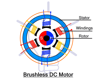
What is Brushless DC Motor (BLDC Motor)? Working, Diagram ... Feb 16, 2022 · Constructional Features of Brushless dc motor Fig. 1 illustrates this type of motor with the help of a simple block diagram. In conventional d.c motor, field magnets are placed on the stator and armature winding is placed on the rotor. However, brushless dc motor has a polyphase winding (armature) on the stator and permanent magnets on the rotor.
Brushless dc motor block diagram - Electronic Products Brushless DC motors are often small, and range from a few watts to tens of watts. BLDC motors have been in commercial use since the 60s and the advent of solid state semiconductors, whereas brushed motors have been in use since the origin of motors in the late 1800s. Download Full Block Diagram Below ← New floating speaker lets you see sound
Brushless Dc Motor Winding Diagram - Pinterest Brushless Dc Motor Winding Diagram Home Electrical Wiring, Electrical Circuit Diagram, Electrical Projects,. Mark A.Kopecki. 14 followers. More information.
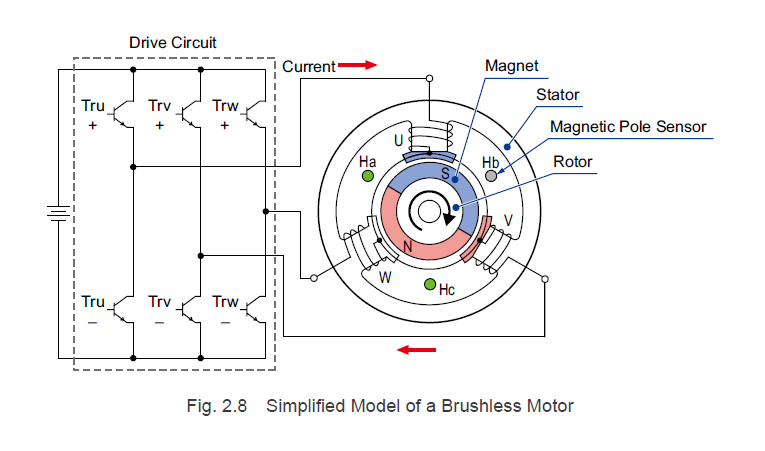
Brushless motor wiring: Its Specifications and complete guide! Winding 1 and 3, then power completing the step. In step 3, switches 3 and 6 close, making the winding of 2 and 3 energize therefore completing the step. In step 4, switches 3 and 2 close, winding 2 and 1 inside the motor to energize. Consequently, it completes the step.
PDF Brushless Motors - tcrconline.com The 3008-32 motor has a Kv of 1090. If you take 1090 x 32 you get 34,880. If you look at the 3008-28 motor, it has a Kv of 1253. If you take 1253 x 28 you get 35,084. Based on these 2 numbers, you can see that the constant for the 3008 size motor is right arounf 35,000.
Brushless DC | BLDC Motor Working Principle - your ... Four-phase, Four-pulse Brushless DC Motor. The stator of this motor is wound with four-phase windings displaced in space by 90° electrical. The phase windings are energized cyclically with four currant pulses. This results in a torque without gaps and a utilization of the winding up to 50 per cent.
Common Winding Schemes - bavaria-direct.co.za It is the first winding scheme that many motor builders and rewinders will ... of the LRK winding scheme, which put outrunner brushless motors on the map.
How To: Rewind Brushless Motors - Hobbyking You might ask why you would rewind a motor. You can pack more copper in the motor and thus get more power out of the motor. Rewinding is nothing new and ...
[No. 15] Reading a winding diagram | Simulation Technology ... This is easily seen to be 8, by counting the salient poles on the field winding on the rotor. But that's cheating — the rotor is not part of the winding diagram! It might be easier to answer some of the other questions first, and then come back to the number of poles. 3. The number of slots. Easy — 48! Count them.
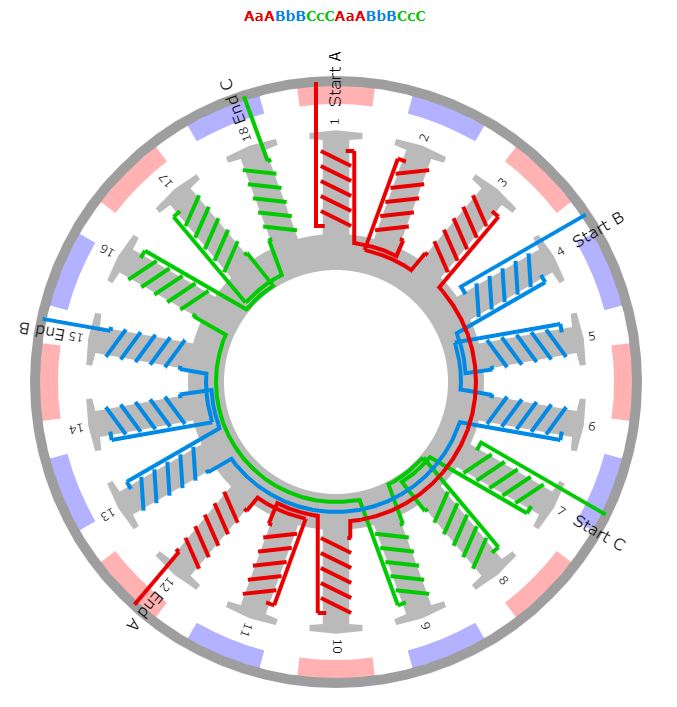
How to determine brushless DC (BLDC) winding pattern ... The essential rules are that the number of poles must be even and the number of teeth must be divisible by 3. Secondary rule is they must not be equal (eg. 6P-6T) or an exact multiple of same (6P-12T). Best combinations seem to be where they are as close to the same as possible within those rules (eg. 2P-3T, 10P-12T, 14P-15T). Share
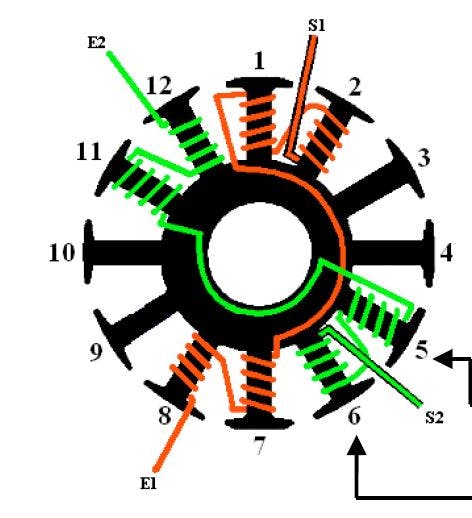
How to Wind a 12N 14P Brushless Outrunner : 3 Steps ... Group together as many strands of wire as you want wrapped on the motor, and start winding clockwise the desired number of turns. Then, move to the next tooth right beside the wrapped one and wind it counter clockwise. Then, go to the tooth on the opposite side (6 teeth away) and wind it clockwise.
Brushless Dc Motor Winding Diagram - Pinterest Nov 20, 2018 - This Pin was discovered by Anas Aswadi. Discover (and save!) your own Pins on Pinterest.
Electric Motor Diagrams In the "A" position the windings function as shown in the diagram. In split phase motors, changing the winding causes the motor to work in reverse. Both windings must be identical as to size of wire and number of turns. Use this when you need a reversible high-torque, intermittently rated capacitor type motor.
Sensational Brushless Motor Diagram Transformer Hook Up Brushless Dc Motor Winding Diagram Teknik Listrik Energi Alternatif Rangkaian Elektronik 2017 Nissan Murano Fuse Box Wiring 2 Pickups 3 Way Switch. Link Bldc 9n6p Esc Diagram In 2020 Electrical Wiring Colours Circuit Diy Solar Charger Boat Trailer Harness Schematic Fluorescent Lamp.
What order do wires go on a brushless motor? - YouTube A quick explanation of the order of wires on a brushless motor. Feel free to contact us with any questions at:
[No. 13] Winding diagram for an AC motor | Simulation ... [No. 13] Winding diagram for an AC motor Last modified at 2 Sep 2019 Here we see a winding diagram for a 3-phase AC induction motor or brushless PM motor (IPM), having 4 poles and 36 slots. This winding could in fact be used with any AC machine, including a synchronous reluctance motor or a wound-field synchronous motor or generator.
PDF Brushless DC Motors - engineering.nyu.edu Elementary Two-Pole, Single-Phase Stator Winding Actuators & Sensors in Mechatronics: Brushless DC Motors K. Craig 8 – Now, consider the diagram of the elementary two-pole, two-phase stator windings. Here we have added a second winding – the bs winding. – The magnetic axis of the bswinding is displaced ½ π from that of the aswinding.
All about RC Brushless Motor Windings - Radio control Feb 03, 2019 · There are two wiring patterns to terminate the windings on a brushless motor. One termination method is known as the Wye wind. The other termination method is known as the Delta wind. In a Wye wind, each motor connector is attached to the start of a phase. All three legs or loads are terminated together as below in the top diagram.










![No. 14] Synthesis of AC motor windings | Simulation ...](https://www.jmag-international.com/wp-content/uploads/engineers_diary/engineers_diary_014b.jpg)


![No. 13] Winding diagram for an AC motor | Simulation ...](https://www.jmag-international.com/wp-content/uploads/engineers_diary/engineers_diary_013.jpg)


Comments
Post a Comment